5047
Bloch-Siegert Phase-Encoded MRI with a Single RF Coil and Frequency-Swept Pulses1Biomedical Engineering, Vanderbilt University, Nashville, TN, United States
Synopsis
RF encoding using the Bloch-Siegert shift has the potential to replace conventional gradient encoding with cheaper RF gradients, and can directly replace gradient pulsing in common MRI sequences. However, current implementations require large frequency offsets to prevent on-resonance excitation, which subsequently requires high RF power for encoding as well as separate imaging and encoding RF coils. Here we show that frequency-swept encoding RF pulses enable the use of a single RF coil for imaging and encoding since the frequency offset can be brought much closer to resonance.
Introduction
RF Encoding using the Bloch-Siegert (BS) shift has been proposed as an alternative to conventional gradient encoding, since it would enable silent scanning without expensive and bulky gradient coils and amplifiers, and it is the only RF encoding method that applies phase shifts without tipping spins1,2, so it may replace conventional gradient encoding in any sequence. The first demonstration of BS phase encoding used block encoding pulses with a large constant frequency offset (600 kHz)1 to minimize on-resonant excitation. This required a separate RF transmit coil for encoding, and high power since the BS phase shift is inversely proportional to frequency offset. It further restricted the encoding to spin echo sequences, so that the same frequency offset could be used to encode both halves of k-space without retuning the coil. In this work, frequency-swept pulses with U-shaped sweeps3,4 were implemented for BS phase encoding, which enabled a single square-root solenoid RF coil5 to be used both for encoding and imaging.Methods
Pulse sequence and frequency-swept pulses
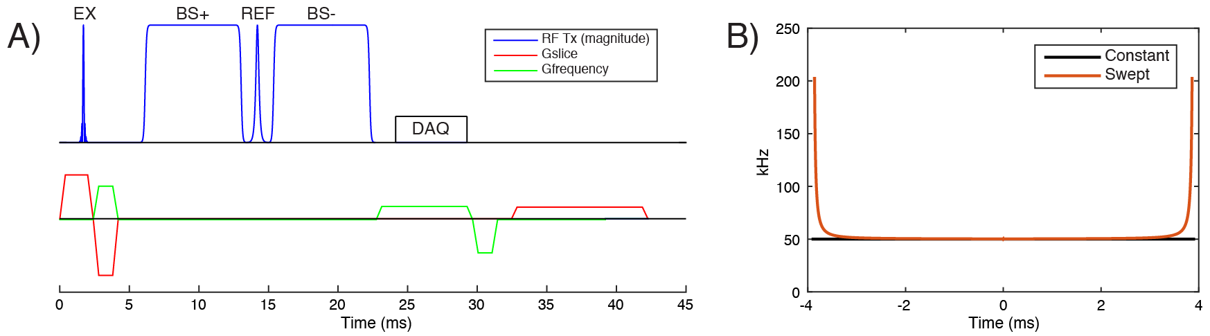
Figure 1a plots the 2D spin echo pulse sequence that was implemented in this study, with 25 ms TE, 1500 ms TR, 8 ms BS phase encoding RF pulses with opposite frequency polarity on either side of a non-selective adiabatic refocusing pulse, and conventional gradient encoding in the slice and frequency dimensions. Figure 1b plots frequency waveforms for the constant and swept BS pulses. The swept pulses start and end with large (200 kHz) frequency offsets, which prevent on-resonant excitation and slowly tip the transverse magnetization into a slightly tilted plane for phase encoding, and back up to the transverse plane at the end of the pulse. Phase is primarily accrued during the flat part of the sweep (50 kHz offset). The sweeps were designed using Eq. 14 in Ref. 4, with design parameter K = 20. For comparison, the constant pulses also used a 50 kHz offset and the same duration.
Coil and Hardware
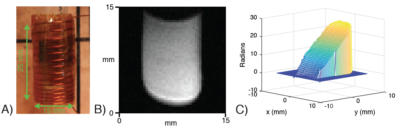
Figure 2 shows the square-root solenoid coil that was built for linear phase encoding, since the BS phase shift varies as the square of RF amplitude. It has 15 turns, 15 mm diameter and 25 mm height. It was tuned to 21.29 MHz (0.5 T), and loaded with a test tube phantom filled with CuSO4-doped water and placed in a tabletop Oxford Maran scanner (Resonance Instruments, Whitney, U.K.). It was driven by a 500 Watt RF amplifier, and a Medusa spectrometer6 was used for all signal generation (RF and gradient pulses) and reception.
Experiments
The 8 ms constant and swept pulses were first used in a pulse-and-acquire sequence, to measure and compare the amount of signal excited by each pulse across frequency offsets. Pulses were sampled with a 2 μs dwell time. Then data were acquired with the spin echo sequence of Figure 1a using each BS pulse, and with conventional gradient phase encoding. The sequence used a slice thickness of 2 mm, and acquisitions targeted a 20 mm FOV. 64 BS phase encoding steps were acquired with each pulse with square root amplitude steps. Reconstruction was performed by regularized matrix pseudoinverse in the phase encoded dimension, using a separate conventional phase-encoded acquisition at each pulse amplitude to calibrate the encoding functions.
Results
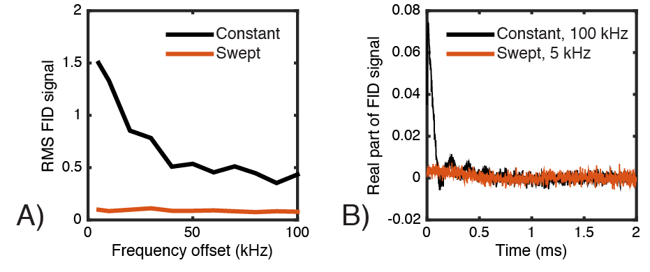
Figure 3a plots the RMS FID signal measured after each pulse, with the same duration (8 ms) and amplitude. As the frequency comes closer to resonance, the constant pulse produces increasing excitation. At 5 kHz, it excites approximately 15x more signal than the swept pulse, which produces nearly no visible FID signal at any offset (Figure 3b).
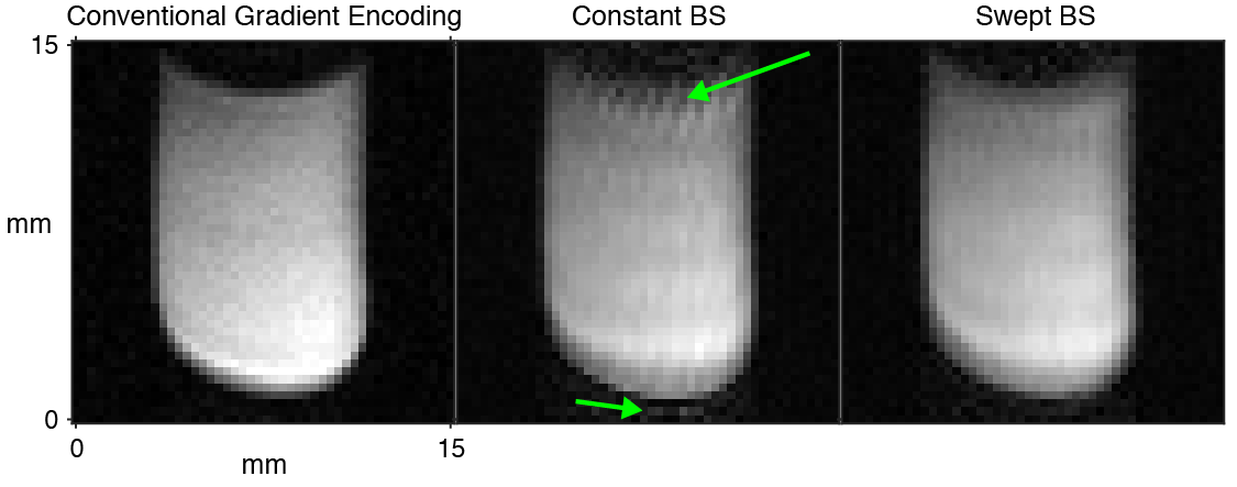
Figure 4 shows a conventional gradient phase-encoded image, and images reconstructed from the BS encoded acquisitions. The BS-encoded images have lower resolution than the conventional image due to power limitations at this pulse duration and offset, but are similar to each other with the same set of acquired RF amplitudes. However, the constant pulse's image contains significant rippling artifacts due to on-resonant excitation (green arrows).
Discussion and Conclusion
In this work we showed that frequency-swept BS phase encoding enables much lower frequency offsets than conventional constant pulses, which enables the same coil to be used for both encoding and imaging, with higher power efficiency. Future work will focus on numerical optimization of the swept pulses for further efficiency improvements, and on increasing spatial resolution.Acknowledgements
This work was supported by NIH grant R21 EB 018521.References
1. R. Kartausch, T. Driessle, T. Kampf, T. C. Basse-Lusebrink, U. C. Hoelscher, P. M. Jakob, F. Fidler, and X. Helluy. Spatial phase encoding exploiting the Bloch-Siegert shift effect. Magn Reson Mater Phy, 27:363–371, 2014.
2. Z. Cao, E. Y. Chekmenev, and W. A. Grissom. Frequency encoding by Bloch-Siegert shift. In Proceedings 22nd Scientific Meeting, International Society for Magnetic Resonance in Medicine, Milan, page 4220, 2014.
3. M. Jankiewicz, J. C. Gore, and W. A. Grissom. Improved encoding pulses for Bloch-Siegert B1+ mapping. J Magn Reson, 226:79–87, 2013.
4. M. M. Khalighi, B. K. Rutt, and A. B. Kerr. Adiabatic RF pulse design for Bloch-Siegert B1+ mapping. Magn Reson Med, 70(3):829–835, 2013.
5. C. Zimmerman Cooley. Portable Low-Cost Magnetic Resonance Imaging. PhD thesis, Massachusetts Institute of Technology, 2014.
6. P. P. Stang, S. M. Conolly, J. M. Santos, J. M. Pauly, and G. C. Scott. Medusa: A scalable MR console using USB. IEEE Trans Med Imag, 31(2):370–379, 2012.
Figures