4798
A Transverse External RF Surface Coil for Prostate MR Imaging at 3T1Radiology, UT Southwestern Medical Center, Dallas, TX, United States, 2Advanced Imaging Research Center, UT Southwestern Medical Center, Dallas, TX, United States, 3Philips Medical Systems, Cleveland, OH, United States
Synopsis
MRI is playing an increasingly important role in the work up of prostate cancer. This increased demand for prostate imaging has caused a debate in the field regarding the necessity of an endo-rectal coil for these studies. While the endo-rectal coil has distinct advantages it also has some drawbacks in both work-flow and cost. Current external coils do not provide images at comparable SNR to endo-rectal coil images (at the same field strength). Here we describe our initial experience with a transverse external RF coil designed to be placed on the perineum for high quality images.
Purpose
Our goal was to develop an external coil design that could be positioned adjacent to the perineum which is in close proximity to the prostate. This requires an RF coil that can be placed in a plane perpendicular to the main Zeeman field, a so called transverse coil.Introduction
MRI images of the prostate obtained at 1.5 T with the endo-rectal coil (ERC) were first reported in 19891. The SNR of these images were about a factor of two better than any external surface coil and much better than the body coil. This was followed by several clinical studies showing improvements in staging accuracy using the ERC (see for example reference 2). In 1992, the ERC was combined with an external coil array3. The first report of imaging with a combined ERC and external array at 3T4 appeared in 2004. In the same year, Sosna et al,5 showed that MR images acquired at 3T with an external array had comparable image quality to those obtained at 1.5 T with an external array and ERC. This confirms the fact that the ERC produces images that have an SNR that is about twice that of an external coil array. Costa et al,6 have shown that the accuracy of detection of prostate cancer improves approximately linearly with the SNR. Accordingly, we have explored novel coil designs and positioning strategies that could potentially provide MR images of the prostate with SNR as close to the SNR of ERC as possible. We found that so called “transverse coils” described by Alfonsetti et al.7-9 might achieve this goal. It should be noted that a similar approach was described for an intra-oral dental coil10Methods
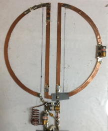
We carried out simulations using Remcom (Remcom, State College, PA) on a two element Figure 8 coil similar to that described by Alfonsetti et al.7 These simulations were virtually identical to those described in reference 7. We then imaged an anthropomorphic prostate phantom (Custom made by Yezitronix, Montreal, Canada) based on their Multi-Modality phantom (Model S-MM-2.3) in a Philips 3T Ingenia scanner with the transverse-field RF surface coil (two element Figure 8 coil, dimensions are given in Figure 1) and with a standard ERC prostate coil. The transverse-field RF surface coil was positioned at the inferior end of the prostate phantom and oriented perpendicularly to the Zeeman field of the scanner, whereas the ERC was inserted into the phantom. A 12 channel posterior and 16 channel anterior array were also used in all acquisitions. Multi-slice axial T2 TSE images were acquired with the following parameters: TR/TE = 2000/110 msec, FOV = 180x180 mm, acquisition matrix = 400x297, slice thickness = 2.5 mm. No acceleration was employed. A second set of images was acquired without RF or gradients to measure noise for subsequent SNR measurements. The scan time was 2 ½ minutes.Results and Discussion
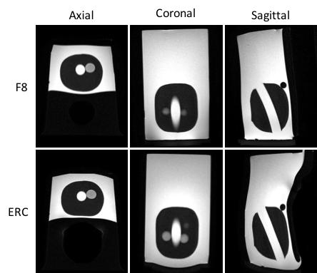
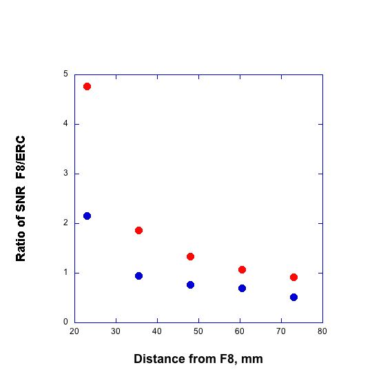
The images acquired on the phantom with the two coil configurations are shown in Figure 2. The SNR was measured for 2 ROIs in each of 5 axial slices within the phantom. The variations in the ratios of the SNR of similar ROIs for the two coil configurations with the distance of the ROI from the Figure 8 RF coil are shown in Figure 2. Note that the sensitivity of each coil decreased with distance from the coil. The SNR of the Figure 8 coil was greater than that of the ERC for ROIs close to the Figure 8 coil but far from the ERC. The Figure 8 coil gave at least 70% of the SNR of the ERC up to 6 cm from the coil.Conclusions
The results presented here show that using a multi-coil array including an external transverse coil designed to be placed on the perineum may produce MR images of the prostate at 3T that have improved SNR over other external coil designs. This coil design could streamline coil positioning and minimize any issues with patient discomfort.Acknowledgements
Grant funding CPRIT R1107.References
1. Schnall MD, Lenkinski RE, Pollack HM, Imai Y, Kressel HY. PROSTATE - MR Imaging With An Endorectal Surface Coil. Radiology. 1989;172(2):570-574.
2. Schnall MD, Imai Y, Tomaszewski J, Pollack HM, Lenkinski RE, Kressel HY. Prostate-Cancer - Local Staging With Endorectal Surface Coil MR Imaging. Radiology. 1991;178(3):797-802.
3. Schnall MD, Connick T, Hayes CE, Lenkinski RE, Kressel HY. MR Imaging Of The Pelvis With An Endorectal-External Multicoil Array. Jmri-Journal of Magnetic Resonance Imaging. 1992;2(2):229-232.
4. Bloch BN, Rofsky NM, Baroni RH, Marquis RP, Pedrosa I, Lenkinski RE. 3 Tesla magnetic resonance Imaging of the prostate with combined pelvic phased-array and endorectal coils: Initial experience. Academic Radiology. 2004;11(8):863-867.
5. Sosna J, Pedrosa I, Dewolf WC, Mahallati H, Lenkinski RE, Rofsky NM. MR imaging of the prostate at 3 Tesla: Comparison of an external phased-array coil to imaging with an endorectal coil at 1.5 Tesla. Academic Radiology. 2004;11(8):857-862.
6. Costa DN, Yuan Q, Xi Y, Rofsky NM, Lenkinski RE, Lotan Y, et al. Comparison of prostate cancer detection at 3-T MRI with and without an endorectal coil: A prospective, paired-patient study. Urologic Oncology-Seminars and Original Investigations. 2016;34(6).
7. Alfonsetti M, Clementi V, Iotti S, Placidi G, Lodi R, Barbiroli B, et al. Versatile coil design and positioning of transverse-field RF surface coils for clinical 1.5-T MRI applications. Magnetic Resonance Materials in Physics Biology and Medicine. 2005;18(2):69-75.
8. Alfonsetti M, Mazza T, Alecci M. Optimization of multi-element transverse field radio frequency surface coils. Measurement Science and Technology. 2006;17(10):N53-N59.
9. Alfonsetti M, Sotgiu A, Alecci M. A theoretical and experimental study on transverse field radio frequency surface coils. Measurement. 2010;43(10):1503-1515.
10. Idiyatullin D, Corum CA, Nixdorf DR, Garwood M. Intraoral Approach for Imaging Teeth Using the Transverse B-1 Field Components of an Occlusally Oriented Loop Coil. Magnetic Resonance in Medicine. 2014;72(1):160-165.
Figures