4444
RF-sensing for Trigger-based Synchronization of Auxiliary Devices, and Pulse-sequence Debugging1Department of Radiology, Brigham and Women's Hospital, Harvard Medical School, Boston, MA, United States, 2Beijing University of Posts and Telecommunications, Beijing, People's Republic of China
Synopsis
Voltage or laser-light triggers are often used to synchronize auxiliary devices to the MR acquisition process. A very simple RF antenna and associated circuit is proposed here instead. The device is used here to trigger ultrasound probe firings, as part of a hybrid ultrasound-MRI system, but could be used for other purposes as well. Compared to scanner-generated triggers, advantages include: 1) vendor- and software release-independent, 2) available in the scan room, 3) no change to product sequences needed, and 4) the little device proved handy for pulse sequence debugging as well.
Introduction
Scanner-generated triggers, either in the form of a voltage or laser-light pulses, are widely employed for the synchronization of auxiliary devices. For example, triggers are required for the hardware that generates visual and/or other sensory signals as part of functional MRI studies, or in the present case, for firing an ultrasound transducer as part of a hybrid ultrasound-MR imaging setup. Such triggers can typically be added fairly easily to a pulse sequence whenever source code is available. Alternately, a small device is described here to sense RF pulses directly in the scan room, and generate triggers from them. As opposed to employing pulse-sequence generated triggers, RF-sensed ones may have a few advantages: 1) The device is naturally vendor-independent and readily portable from scanner to scanner regardless of software release version, 2) it is generated at a convenient location, the scan room, and depending on scanner make/model system-generated triggers might be available only in the computer room, 3) product sequences can be used without modification, i.e., without having to be granted access to source code through a research agreement, and 4) the little device further proved handy for pulse sequence debugging.
The device consists of a simple antenna whose signal can be input into an oscilloscope or connected to a custom circuit board. The circuit was designed to convert the signals into rectified binary triggers, to synchronize auxiliary devices to the MRI acquisition process.
Methods
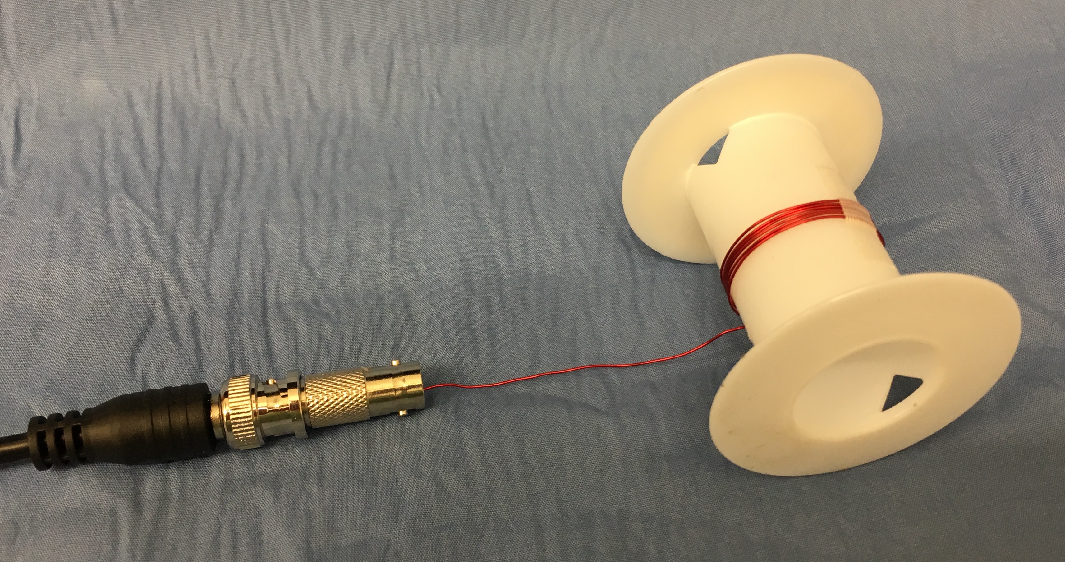
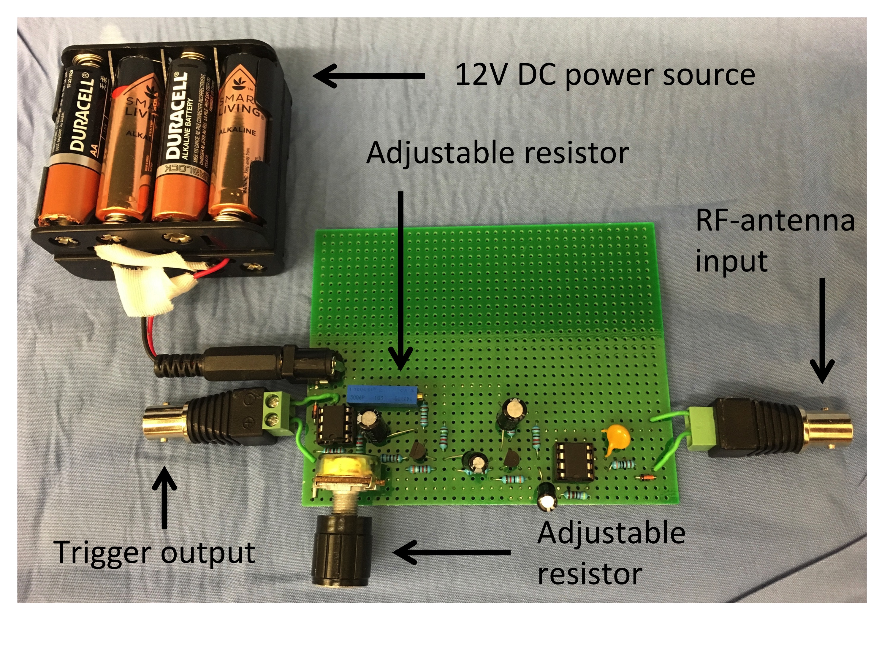
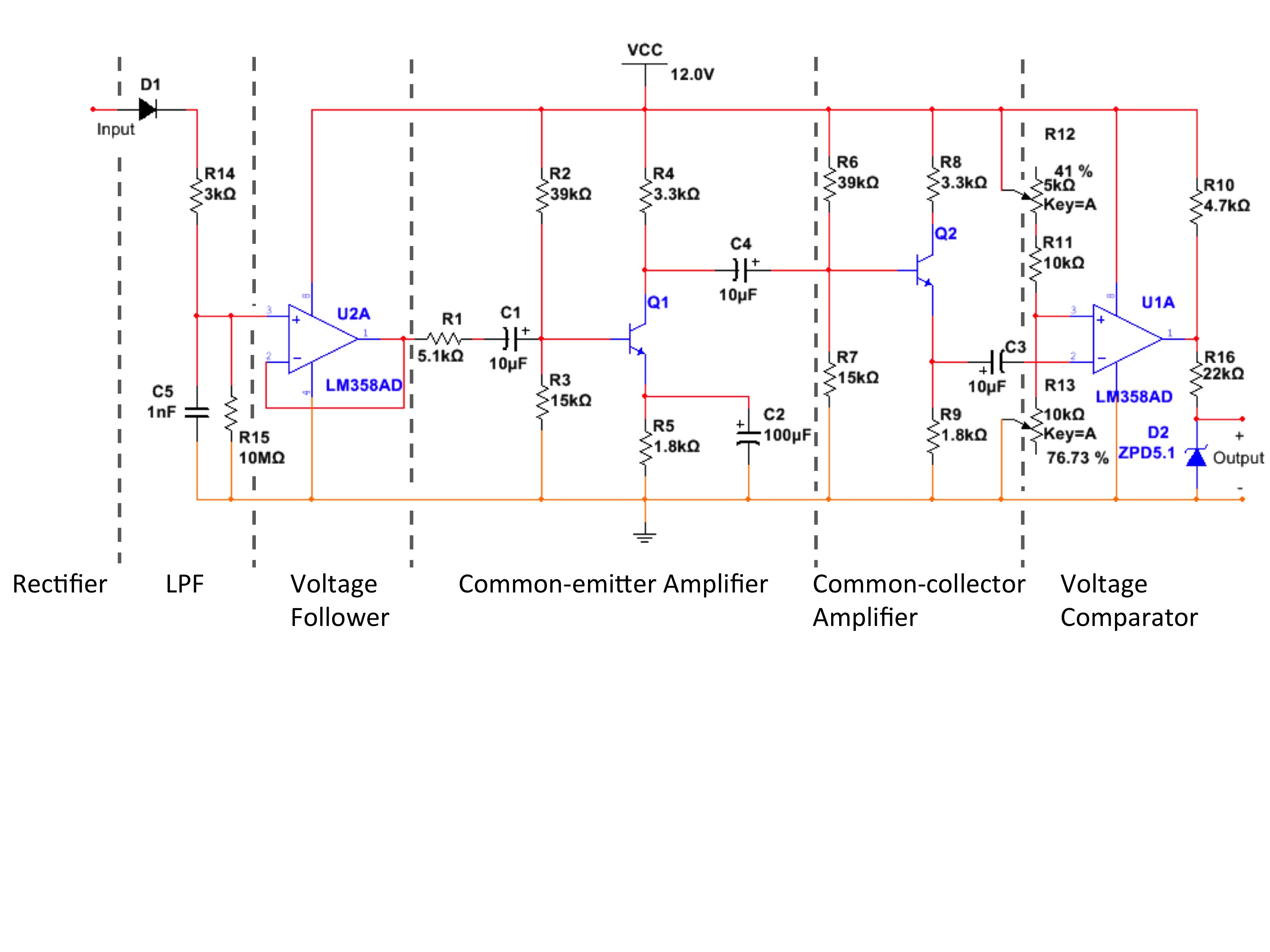
An RF antenna coil was fabricated from 24 AWG gauge enameled copper magnet wire (Philmore), 62 mm length, wound 6 times around a cylinder of 29 mm diameter, with the end connected to a male-to-male adapter and a BNC cable (Figure 1). A photograph of the custom circuit is shown in Fig. 2, and associated schematic diagram in Fig. 3.
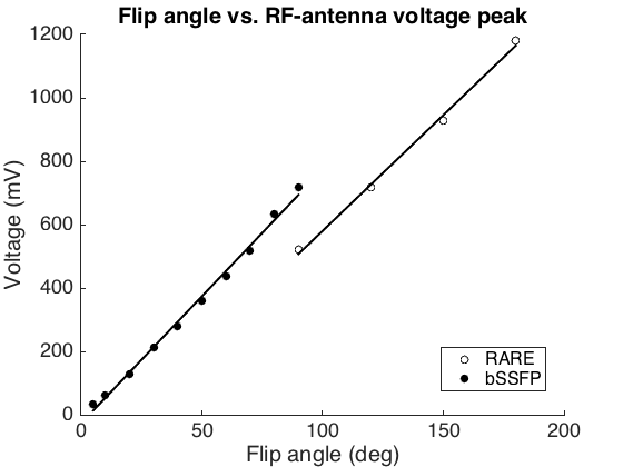
In a first step, the relationship between detected voltage and nominal flip angle was studied. Using a product version of a RARE sequence followed by a balanced SSFP (bSSFP) sequence, RF signals as picked up by the antenna were captured by an oscilloscope (TDS 2004C, Tektronix), and the peak amplitude was recorded for a number of different flip angles. In a second step, the ability of the custom built circuit to correctly transform this raw signal into triggers was tested on an RF-spoiled gradient echo sequence (FLASH, TR = 10 ms, flip angle 60°, acceleration factor 3.2, 60 TRs / 600 ms per image). The triggers as created by the antenna and associated circuit were utilized to fire a hybrid ultrasound-MR imaging setup. The triggers were fed to a pulser-receiver (5077PR, Olympus Scientific Solutions) which in turn pulsed a 1 MHz ultrasound transducer, and forwarded the acquired ultrasound signals to a standard PC equipped with a digitizer card (NI 5122, National Instruments). This way, during the 12 seconds of MR acquisition, a total of 1200 ultrasound A-mode lines were acquired, (5000 samples / 19.25 cm depth at 20MS/s). All experiments were performed on a 3T system (45 mT/m, 200 T/m/s), using a multimodality CIRS gel phantom.
Results
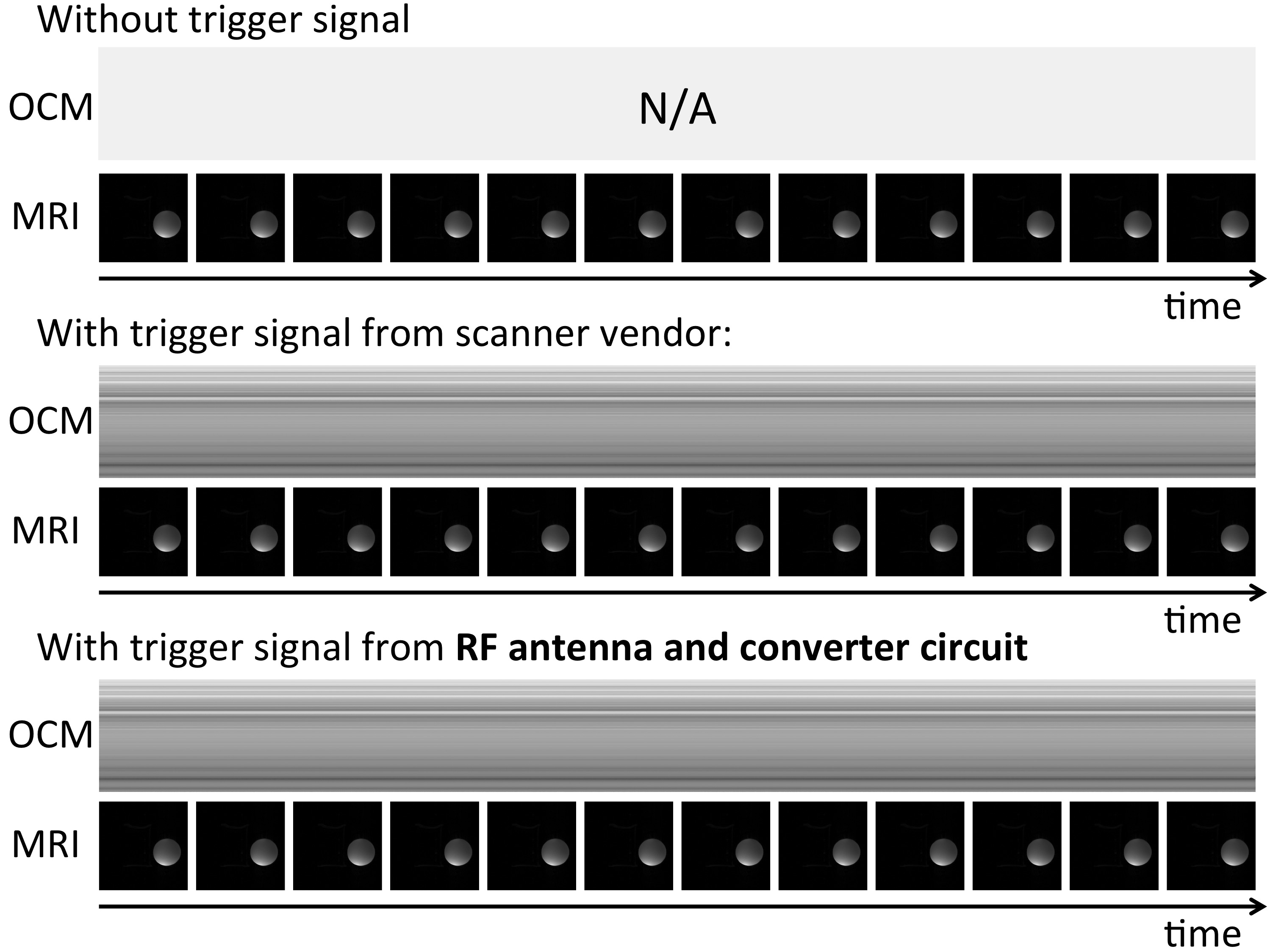
Figure 4 shows the linear dependence between nominal flip angle and peak voltage. The slope depended on RF shape and coil placement. A linear dependency was found, as expected. As for the simultaneous acquisition of ultrasound and MRI, the circuit correctly emitted one trigger per TR period, resulting in 1200 acquired ultrasound A-mode lines. Figure 5 shows the acquired data, compared to an equivalent acquisition using MR system-provided triggers instead, as well as no trigger at all. The ultrasound data acquired using our own trigger setup is equivalent to the data acquired using the vendor’s trigger, but with added convenience as described above.Discussion and Conclusion
The RF antenna is a simple yet useful device for pulse sequence analysis and debugging, due to the linear dependency between flip angle and the integral of the RF pulse. Given one known pulse to calibrate the slope (see Fig. 4), the flip angle associated with unknown pulses can readily be found, a useful trick when debugging a pulse sequence and/or trying to figure out how an unknown pulse sequence functions. The trigger circuit, together with the coil, allowed to synchronize auxiliary devices, in a manner that is thoroughly vendor-independent. This proves especially useful when source code is not readily available.Acknowledgements
Support from NIH grants P41EB015898, R01EB010195 and R01CA149342 and SNSF grant P300P2_164647 is acknowledged.References
No reference found.Figures