4439
RF Coil Performances in Compact Hybrid MR/PET Scanner Design Using an Integrated Shielding1Institute of Neuroscience and Medicine, Forschungszentrum Juelich GmbH, Juelich, Germany
Synopsis
The goal of this study is to demonstrate hybrid MR/PET scanner design optimization methods from an RF coil perspective with a focus on UHF MRI. Here, coil performances are investigated depending on different shielding distances to present simulation and measurement methods to include RF coil performances into the hybrid MR/PET scanner design. Moreover, integration of PET detector shielding and RF coil shield is investigated. The results of this study clarify that a trade of between a compact design, PET and RF coil performances is necessary and that RF coil performances can be optimized by an integrated shielding with an optimized configuration.
Purpose
In hybrid MR/PET scanner design an RF shield is commonly installed between the RF coils and the PET data acquisition systems [1-2]. This prevents electromagnetic (EM) coupling between the two parts by shielding the interior of the cassette from the EM field generated by the RF coils. In whole-body hybrid MR/PET scanners the space available for a PET ring is significantly smaller. As such, a compact design is essential and is driven by the fact that the already high price of a hybrid scanner can be reduced with a reduction in the bore size. The bore diameter is directly proportional to the magnet price, which is the dominant cost in an MRI system. This aspect is even more critical for whole body, ultra-high field (UHF) hybrid scanners, such as the 7 T and 9.4 T variations. Furthermore, a compact PET ring close to the subject increases PET scanner sensitivity and reduces the amount of required detectors. When the PET detectors with its electronics are positioned as close as possible to the object to be imaged, the RF shielding of the PET electronics will be in close proximity to the RF coil. To reduce the total required volume, the PET electronics shielding and the RF coil shield can be integrated into a single component. However, the shielding design has a significant influence on the RF coil performance. The aim of this study is to investigate the influences of the shielding on typical RF coil performance for hybrid scanners and to compare the results from a 4 T scanner with those from an UHF 9.4 T scanner.Methods
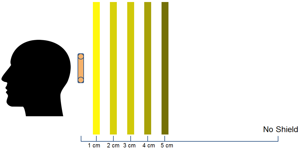
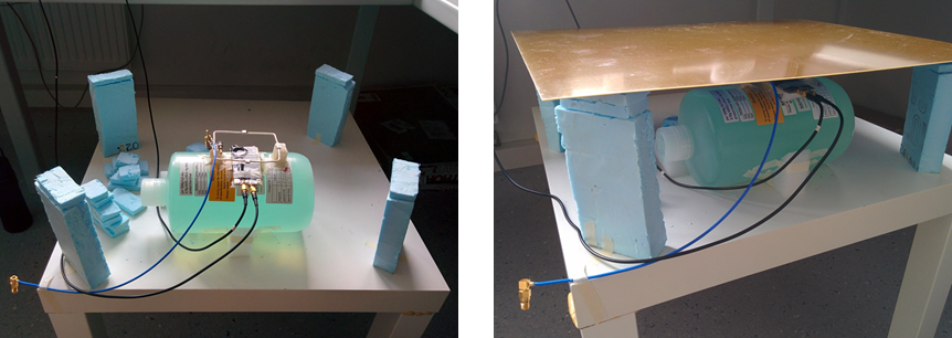
To evaluate coil performance for different shielding configurations, the B1+ field, specific absorption rate (SAR), and quality factor (Q value) were simulated and measured. First, CST microwave studio simulations investigated the dependence of B1+ field strength and SAR in the human head on the distance from the shielding to a surface coil. Simulations for both 168 and 400 MHz were performed. The simulation setup consisting of a human head, surface coil, and planar copper shield is demonstrated in Figure 1. The same simulation was then repeated with the planar copper shield replaced by the PET cassettes which are covered by copper plating. The measurement setup for analysing changes in the Q value is demonstrated in Figure 2. Q value measurements were performed with tuned and matched conditions for a surface coil. The Q value measurements were taken for both unloaded and loaded coils. After every adjustment to the shielding configuration, the coil was retuned and rematched to the new environment.Results
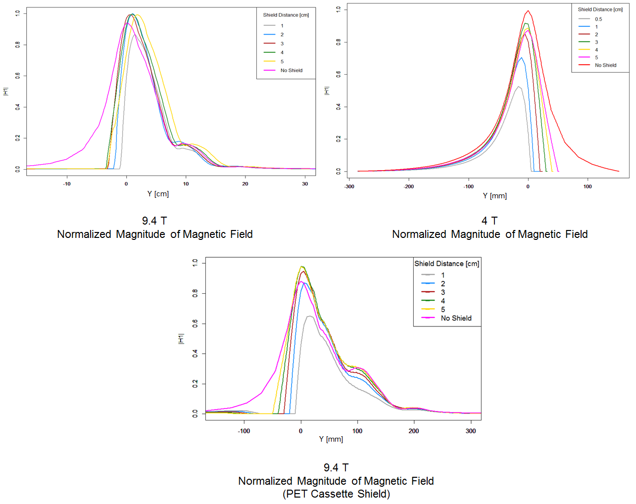
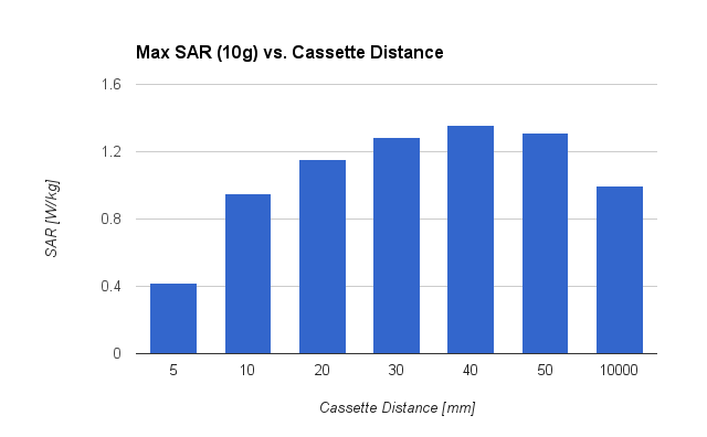
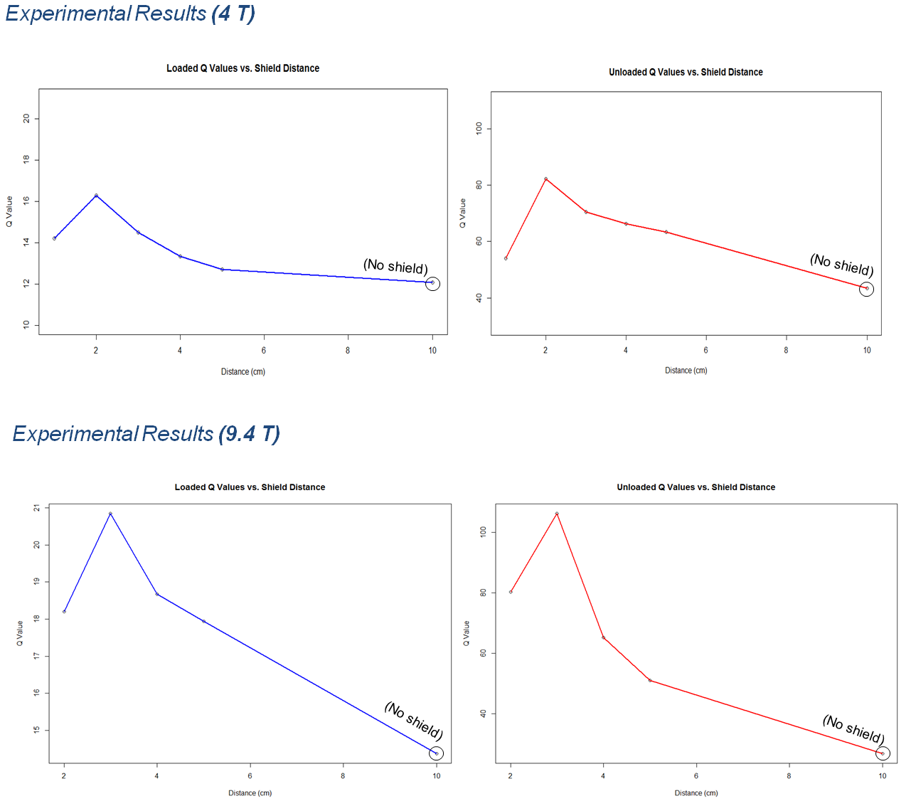
Figures 3 shows the normalized B1+ field of the coil depending on the shielding distance as well as the normalized B1+ field if PET cassettes are used as an RF coil shield. Figure 4 demonstrates the dependency of the SAR on the cassette distance. In Figure 5 the unloaded and loaded Q value is demonstrated for 4 T and 9.4 T.Discussion
As demonstrated in Figure 3, the B1+ field profile inside the human head changes with an increase of the frequency. The less homogeneous B1+ field at 400 MHz versus at 168 MHz is due to a decrease in wavelength - which is already in the range of the observed object. While at 4 T the highest B1+ can be achieved without a shield, where the RF coil is not coupling to a shield this behaviour was found to change at 9.4 T. At 400 MHz radiation losses have a more significant impact. It can be derived from Figure 3 that a shielding distance of 5 cm shows the highest b1+ field as well as a deeper RF penetration depth. Replacing the RF shield by PET cassettes, the B1+ field distribution changes. In Figure 4, it can be seen that for 4 of the 6 distances simulated the highest peak SAR increased in comparison to the no shield case. As observed in Figure 5, the shield distance also influences the Q value of the coil. The optimal distance changes with frequency. At 4 T, a shorter distance shows the highest Q value. At 9.4 T, the optimal distance for highest Q value is increased.Conclusion
The work presented in this study shows the influence of shielding configurations on RF coils in hybrid MR/PET scanners. A consequence for compact MR/PET scanner design is that size reduction and PET performance such as sensitivity and spatial resolution detection cannot be optimized separately from the performance of the RF coils of the MRI scanner.Acknowledgements
No acknowledgement found.References
[1] A. Berneking, R. Trinchero, P. Cerello, C. W. Lerche, and N. J. Shah “Low-Pass Shielding Design for MRI Applications Optimized for Strong RF Shielding Effectiveness”, presented at the ESMRMB conference, Vienna, Germany, September 29–October 1, 2016.
[2] A. Berneking, R. Trinchero, N. J. Shah, P. Cerello, and C. W. Lerche, “Design and Characterization of a Frequency Selective RF Shield for PET Detector Modules in Hybrid MR-PET Imaging”, presented at the PSMR conference, Cologne, Germany, May 23–25, 2016.
[3] H. Herzog, et al., “High resolution BrainPET combined with simultaneous MRI”, Nuklearmedizin, vol. 50, pp.74–82, Feb. 2011.
Figures