4437
CANTILEVER SYSTEM TO REDUCE PHASE NOISE CAUSED BY VIBRATIONS IN 11.1TMalathy Elumalai1, Joshua E Slade1, Huadong Zheng1, and Thomas H Mareci2
1AMRIS facility, University of Florida, Gainesville, FL, United States, 2Department of Bio-chemistry and Molecular Biology, University of Florida, Gainesville, FL, United States
Synopsis
Magnetic Resonance Imaging at higher field strengths has several design challenges that must be addressed for optimal performance and image resolution. We have developed a cantilever system that is suspended in the magnet to eliminate phase noise that are produced due to vibrations generated by gradient coils. The cantilever system has features such as detachable quadrature RF coils, animal cradle system with in-built water & anesthesia and tuning/matching capability outside the bore. The system is not only centered in all three axes but also has tuning capability in the z-direction from outside the bore so we could move the subject in and out to center in the bore.
Introduction
MR imaging at higher field strengths have several design challenges that must be addressed for optimal performance and image resolution. Once such challenge is the phase noise/artifact produced due to vibrations generated by gradient coils. When certain pulse sequences are used, vibrations were more pronounced due to rapidly switching electric currents passing through gradient coils.For example, we were able to observe significant phase noise while using FSEMS (Fast Spin Echo Multi Slice) sequence. The FSEMS sequence is a regular spin echo sequence with a series of 180° refocusing pulses after a single 90° pulse to generate a train of echoes.In this technique, the phase encoding gradient is changed for each of the echoes produced. It results in rapid switching of gradients which leads to phase noise/artifact. In order to eliminate the phase noise, we decided that the RF coil has to be isolated from the gradient coil. So,we developed a cantilever system that could not only be suspended in the gradient bore but also house detachable quadrature RF coils, modular animal cradle, detachable anesthesia and water supply. The system is built in a way to tune/match the coil outside the bore.Materials and Methods
The cantilever system was designed to accommodate the length of 11.1T magnet, which is 2.6 m long. In order to achieve better stability, G-10 fiberglass tubing was used to mount the RF coil and other supporting systems. The long G-10 tube was mounted inside the magnet bore using support from aluminum stand on either ends (See Fig.1). The stand is built with a lever system to center the cantilever in the magnet.The system is equipped to accommodate 110 mm OD, 79 mm ID and 126 mm long quadrature birdcage TX-only RF coil used for rat whole body imaging. The RF coil is mounted in the center of the cantilever (See Fig. 2a), with tuning rods running along the length to be accessed outside (See Fig. 2b). The RF coil could be easily detached and replaced with another coil by pushing the knobs in the RF end of the cantilever. Also, water and vacuum disconnects are mounted on the AS( Animal Support ) end of cantilever for easy setup and access (See Fig. 2c). The center of the cantilever is machined in a way to mount the modular animal cradle 3D printed using MakerBot Replicator 2. The animal cradle also houses hot water channels, bite bar, nosecone and ear bars for better animal positioning/imaging (See Fig.3). In order to position the subject in the iso-center of the magnet, coarse and fine tuning of animal cradle is provided from outside the bore using a tuning rod structure. The cradle could also be positioned in pre-allocated spots meant for brain, cardiac, lung and leg imaging. The animal cradle is designed to hold RX-only array coil in the center of the TX-only coil.In order to prevent damages to the system during installation, we 3D printed crash supports using PLA. They were systematically placed throughout the length to prevent damages to RF coil,tuning rods and animal cradle. We designed a flange with Teflon wheels and placed it in the RF end of the cantilever. It not only helps in rolling the cantilever in the bore smoothly but also helps in positioning the cantilever in the aluminum stand. The system has all features necessary for rat and mouse in vivo imaging.Results
In the AMRIS Facility, the linear H-1 coil was tested using 11.1T, 120 mm bore magnet interfaced with Varian console. The results before and after using cantilever system are shown. Without cantilever, a linear volume coil and 39mm sphere sample was tested using FSEMS (Fast Spin Echo Multi Slice) sequence, matrix size of 256 x 256 and FOV 20 x 20 mm. The Fig.4 shows imaging phase noise observed because of vibrations induced in the coil. For the same experiment using the cantilever, the phase noise has been eliminated, as shown in Fig.5. Using a Quadrature H-1 TX-only coil, we ran in vivo experiments to evaluate the cantilever performance. We used RARE( Rapid Acquisition with Relaxation Enhancement) , a form of multiple echo sequence, with FOV 25 x 25 mm and matrix size 256 x 256. Fig 6 shows that no phase noise was observed while cantilever system was used to obtain data in in vivo experiments.Future work
We are working on a version where we will be able to access the tune/match rods of the RX-only surface coil outside the bore and also to accommodate different sized TX- only coils.Acknowledgements
This work was performed in McKnight Brain Institute at NHMFL's Advanced Magnetic Resonance Imaging and Spectroscopy facility, which is supported by National Science Foundation Cooperative Agreement No. DMR-1157490 and the State of Florida.References
(1) A modular MRI probe design for large rodent neuro imaging at 21.1 T (900 MHz) P. L. Gor'kov1, C. Qian1, B. L. Beck2, M. Clark1, I. S. Masad1,3, V. D. Schepkin1, S. C. Grant1,3, and W. W. Brey11National High Magnetic Field Laboratory, Tallahassee, FL, United States, 2McKnight Brain Institute, University of Florida, Gainesville, FL, United States, 3Chemicaland Biomedical Engineering, Florida State University, Tallahassee, FL, United StatesFigures
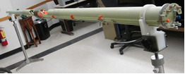
Fig 1: Cantilever system supported by aluminum stands on either end
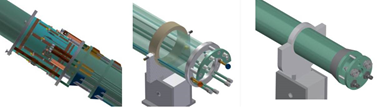
Fig.2a: Detachable RF coil, Fig.2b: Tuning /matching rods for
outside bore access, Fig.2c: Water
and Vacuum disconnects outside bore
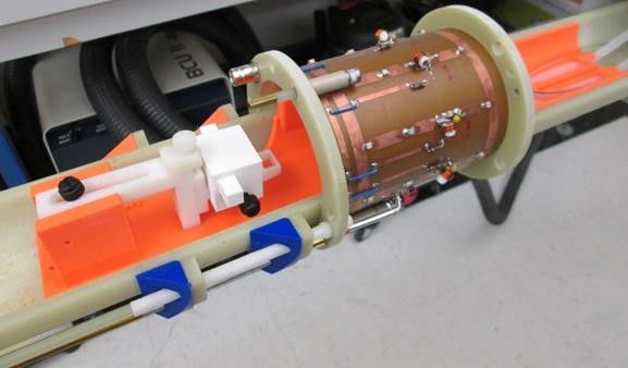
Fig 3: 3D printed animal cradle centered in the RF coil
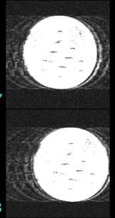
Fig 4: Phase
noise observed without cantilever system while imaging phantoms.
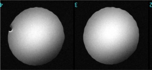
Fig 5: Phase
noise eliminated using cantilever system while imaging phantoms.
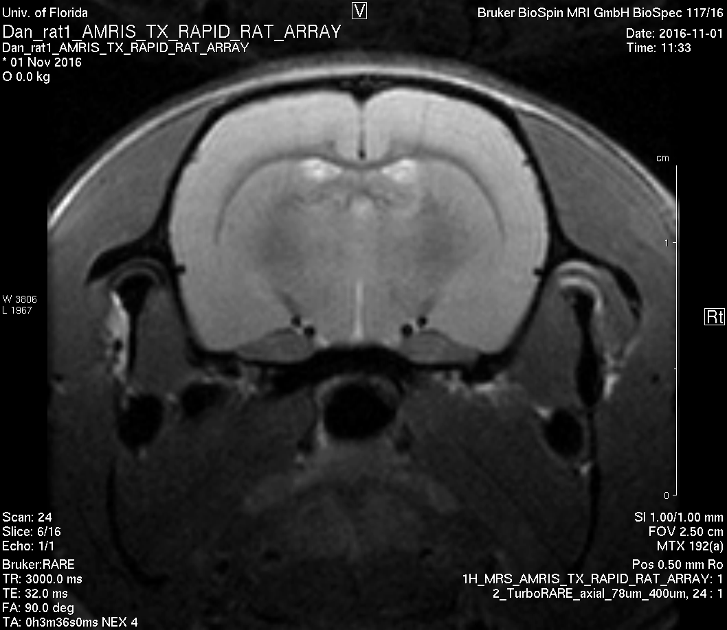
Fig 6: Phase noise eliminated using cantilever system while in vivo imaging.