4436
A MRI Compatible Class-EF Power Amplifier Designed to Drive a Wireless Power Transfer System1Electrical Engineering, Stanford University, Stanford, CA, United States, 2GE Healthcare, Aurora, OH, 3Radiology, Stanford University, Stanford, CA
Synopsis
A compact wireless power transfer (WPT) system being used to power wireless patient coils would require a compact power amplifier that can operate inside the MRI bore. A Class-EF power amplifier is designed and implemented that uses air-core inductors and is capable of driving the coupled resonant coils used for WPT with similar efficiency to a system that uses a large and expensive power amplifier that is outside the scan room. This new power amplifier is very compact and is also very cost-effective.
Introduction
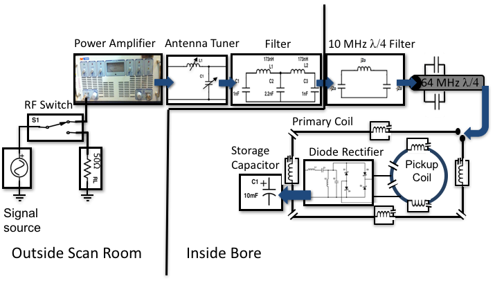
If wireless patient coils could be realized, they would reduce setup time, improve workflow, and eliminate connector reliability concerns for coils. Battery powering these coils would limit scan time, so it is desirable to use wireless power transfer (WPT), which uses inductively coupled resonant coils to transmit and receive power at a particular frequency. We have previously shown the WPT system in Figure 1, which is able to deliver power inside an MRI bore with minimal RF interactions through the use of RF gating1. However, this system uses a large and expensive power amplifier that cannot be operated inside the magnet. Class-E power amplifiers are designed to shape the voltage and current waveforms so that there is never simultaneously high current and voltage, minimizing power loss and maximizing efficiency2. Class-EF power amplifiers have an added resonant network in series or parallel with the power amplifier load to reduce voltage or current stresses on the device3. Here we present a Class-EF power amplifier that can provide power inside the MRI bore and is capable of driving the coupled resonant coils used for WPT.Methods
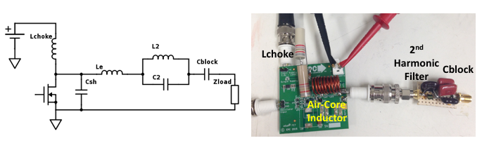
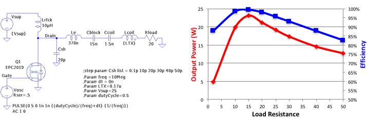
Figure 2 shows the power amplifier, which was designed based upon the Class-E amplifier. The Class-E design has discrete design equations available that account for the shunt capacitance of the device2. The parallel LC network in series with the amplifier load is designed to resonate at the second harmonic of the amplifier, reducing voltage stress on the device. The amplifier is designed to output 20 W to a 20 W resistive load, at a frequency of 10 MHz and a supply voltage of 26 V. An eGaN FET was chosen for the amplifier because of the low output capacitance and low on resistance of the FETs, leading to higher amplifier efficiency4. We used the EPC9053 Class-E amplifier development board, which includes the EPC2019 eGaN FET, to prototype the amplifier. We constructed a 45x30cm primary coil incorporating 64 MHz traps and tuned for series resonance at 10 MHz. Power harvesting was accomplished by a one turn, 20.3cm diameter flexible pickup loop, also tuned to 10 MHz. A quarter-wavelength block was designed to up-convert the coupled coil impedance from a few ohms to the 20 W required by the power amplifier. A series capacitor was also used to ensure that we were presenting a real impedance to the power amplifier.Results
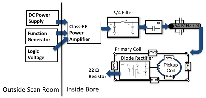
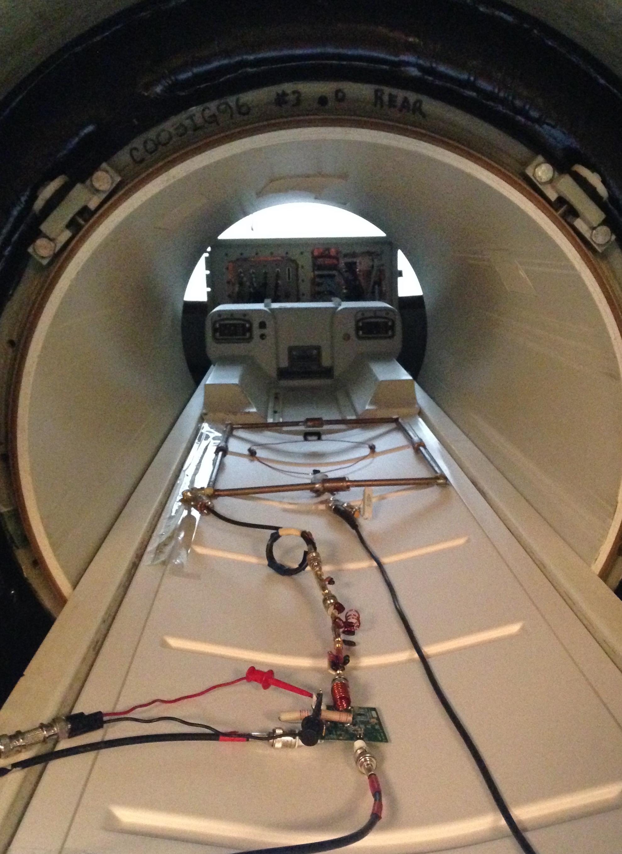
Figure 2 shows the completed power amplifier. An air-core inductor was easily made for Le, however the RF choke value was limited by what was available without using ferrite components. The load resistance was also limited by the parasitic capacitance of the FET to 20 W, instead of up converting to 50 W. The efficiency and power output of the power amplifier is highly dependent on this load resistance, which was modeled in the LTSpice and is shown in Figure 3. In bench-top tests, the power amplifier efficiency was measured to be about 93.75% when powering a resistor and the efficiency of the system shown in Figure 4 was measured to be 26% when delivering about 1 W to the resistor load. This is slightly lower than the efficiency of the system shown in Figure 1, which was about 33.5%, since this new system does not include any automatic impedance matching to ensure that the power amplifier is seeing exactly 20 W. In the magnet, the efficiency of the system in Figure 1 drops to 16.92% due to the increased cable lengths and the proximity of the primary coil to the shield, which causes a shift in tuning. Figure 5 shows the compact power amplifier powering the coupled coils inside the bore, which had a measured system efficiency of 18.54%, which is very similar to the original system efficiency.Discussion & Conclusions
A Class-EF power amplifier is presented that is capable of driving coupled coils used for wireless power transfer inside an MRI bore. However, changes in the coil positions or pickup loop loading will cause the equivalent impedance seen by the power amplifier to change, which could potentially damage the amplifier. Because of this, future work will include creating an automatic impedance matching system that could function inside the MRI environment and ensure that the power amplifier sees its ideal load, improving efficiency and preventing damage to the power amplifier. The present work shows that the Class-EF approach can be very compact, and will simplify power routing by requiring only a DC supply line into the magnet room. Finally, this approach can be very cost-effective, with implementation for under $200.Acknowledgements
We would like to thank GE Healthcare for their research support. This project is supported by grants R01EB008108, P01CA159992, and R01EB019241.References
1. K. Byron, P. Stang, S. Vasanawala, J. Pauly, and G. Scott. A High Power RF Gated Wireless Power Transfer System. Proc. Intl. Sco. Mag. Reson. Med. 24. 2016.
2. Sokal, N. O., and A. Grebennikov. Switch mode RF Power Amplifiers. 2007.
3. S. Aldhaher, D. C. Yates and P. D. Mitcheson. Modeling and Analysis of Class EF and Class E/F Inverters With Series-Tuned Resonant Networks. IEEE Transactions on Power Electronics. May 2016; vol. 31, no. 5, pp. 3415-3430.
4. Lidow, Alex, and M. A. de Rooij. Performance Evaluation of Enhancement-Mode GaN transistors in Class-D and Class-E Wireless Power Transfer Systems. Bodo Magazine. May 2014; 56-60.
Figures