4434
Tunable Electropermanent System for Magnetic Resonance Imaging and Magnetic Particle Propulsion1Weinberg Medical Physics, Inc., North Bethesda, MD, United States, 2Biomedical Engineering, George Mason University, VA, United States
Synopsis
Directing magnetic nanoparticles to sites within biological tissues requires both strong magnetic field gradients and accurate images of the particles and underlying anatomy. Most modern MR imaging systems require always-on magnetic field sources such as permanent magnets or superconducting coils. These field sources limit the ability to control magnetic particles within the imaging volume. Due to these field sources having a high strength always-on magnetic field, there are additional safety concerns when attempting to integrate these sources into an intraoperative arena. We built a new magnetic field source design that is capable of adjusting its magnetic field strength while retaining a low power usage to improve portability.
Purpose
Ideally, a system for MRI-guided particle delivery would be able to alternate between MRI function (with a static field), gradient propulsion for intervention (with no static field), and classic magnetic particle imaging (again with no magnetic field). Resistive magnets would be one solution to create and remove a static field, but at a high cost in terms of cooling and power requirements. Superconducting coils would take a long time to start and quench.
We therefore considered the use of electro-permanent magnets as a primary magnetic field source for MRI [1]. Compared to always-on permanent magnets and high-power resistive or superconducting electromagnets, electropermanent magnets allow for the magnetic field within a region of interest to be changed and adjusted dynamically. Here we present a portable modular two-sided electropermanent system with 72 independently adjustable elements for imaging and controlling magnetic nanoparticles.
Methods
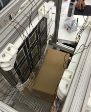
An electropermanent sub-unit consists of a hard magnetic material (NdFeB) surrounded by softer magnetic materials (Alnico 5-7). Each soft magnetic material element is wound with an individually actuated electromagnetic coil. Current flowing through the coil magnetizes the Alnico magnet to a specified remanent magnetization. The NdFeB magnets provide the main magnetic field and are used to reduce the overall size of the electropermanent system. The alnico magnets provide the needed flexibility to shim the region of interest to the imaging strength or to reduce the overall field strength within the region of interest to earth field levels. Using this modular approach and building an array from smaller sub-units, the magnetic field within the region of interest can be designed for a given geometry. In the current arrangement, we created a two sided system (Figure 1). Held together by an adjustable non-magnetic frame, the two sided electropermanent array design can create field between 0.5 mT and 150 mT. The separation distance between the two halves can be varied between 1 and 40 cm. By adjusting the magnetization of the alnico magnets, the field within the region of interest can be manipulated. Starting with equations describing the magnetic field around a permanent magnet, a linear least squares algorithm was used to solve for the required alnico magnetizations assuming a constant geometrical arrangement of the magnets. Two main conditions are considered: ‘On’ with a field strength of 150 mT, and ‘Off’ with a field strength less than 0.5 mT. By passing 600 amps of current within each electromagnet, a field of 0.5 T within the alnico cores can be created. By adjusting the strength of the applied current, the resultant magnetization can be controlled.
Results
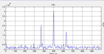
Pulses of 30 ms are sufficient to fully magnetize the alnico blocks, when powered by fourteen 12 volt car batteries capable of supplying 800 amps, switched by an IGBT with a timing resolution of 20 ns. An NMR spectrum using the system is shown (Figure 2).Acknowledgements
Research was supported by the National Institute Of Neurological Disorders And Stroke of the National Institutes of Health under Award Number SB1NS073289. The content is solely the responsibility of the authors and does not necessarily represent the official views of the National Institutes of Health.References
1. Ara Knaian, 2010. “Electropermanent Magnetic Connectors and Actuators: Devices and Their Application in Programmable Matter.” Massachusetts Institute of Technology thesis. http://cba.mit.edu/docs/theses/10.06.knaian.pdf.
Figures