4427
Efficient Analysis of Dielectric Materials in Coupled RF Coil Configurations1Leiden University Medical Center, Leiden, Netherlands, 2NYU School of Medicine, 3Delft University of Technology
Synopsis
Dielectric materials enable additional control of the RF field in a particular RF coil. In this work we present a hybrid domain decomposition method, which allows for an efficient analysis of dielectric materials in the presence of coupled RF coil structures or coil array configurations.
Introduction
MRI at high fields requires new approaches to RF coil design to maximize RF performance. Over the past years, various technologies have been developed, ranging from active control via parallel RF transmission (pTx), to passive approaches using dielectric materials. Previous work also indicates that the combination of both can yield further improvements.1,2 However, the analysis of a dielectric shim in resonant coil structures such as surface arrays can involve long simulation times due to mutual coupling. This impedes a constructive analysis on the design of the dielectric in such scenarios.
A domain decomposition method has previously been presented which reduces the computational domain to that of the dielectric shim, allowing for much faster evaluation of its effect.3 This approach is especially powerful in a decoupled scenario in which the coil’s current distribution is minimally affected by the dielectric. In this work, we extend the domain decomposition method using circuit co-simulation techniques to account for tuned coil models as well as array configurations. Examples are shown for a tuned 7T birdcage analysis and a four-channel dipole array design study.
Methods
The effect of a dielectric in a background RF field generated by a port with index p can be formulated as a field ‘perturbation’ and solved for via domain decomposition as
$$E_p =(\mathbb{I}-\mathbb{G}^{E,J} χ)^{-1} E_p^\tt b$$
where $$$\mathbb{G}^{E,J}$$$ denotes the Green’s tensor for electric current density to electric field, $$$χ$$$ denotes the electric susceptibility which characterizes the dielectric shim, and $$$E_p^\tt b$$$ is the background electric field generated without the dielectric whereas $$$E_p$$$ denotes the final perturbed field. The computational complexity amounts to inverting the system matrix $$$(\mathbb{I}-\mathbb{G}^{E,J} χ)$$$ once, afterwards the resulting inverse can be reused on all ports for the given dielectric.
The perturbed B1+ fields as well as the port voltages and currents can then be obtained via direct evaluation of a set of matrix-vector products, given by
$$B_{1,p}^+ =B_{1,p}^{+,\tt b}+\mathbb{G}^{B_1^+,J} χ E_p$$
$$V_p=V_p^{\tt b}+\mathbb{G}^{V,J} χE_p$$
$$I_p =I_p^{\tt b}+\mathbb{G}^{I,J} χE_p$$
with $$$\mathbb{G}^{B_1^+,J}$$$, $$$\mathbb{G}^{V,J}$$$, and $$$\mathbb{G}^{I,J}$$$ denoting the Green’s tensors for electric current density to B1+ field, port voltage and current, respectively. Using this set of voltage and current relations and EM fields, a circuit co-simulation analysis can be set up in a straightforward manner to evaluate the circuit domain relations.4,5
All Green’s tensors have been evaluated using FDTD (XF7, Remcom inc., PA, USA) and customized codes have been developed in Matlab (R2016, Mathworks inc., MA, USA).
Results
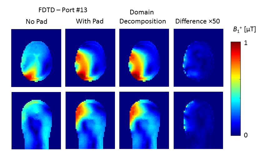
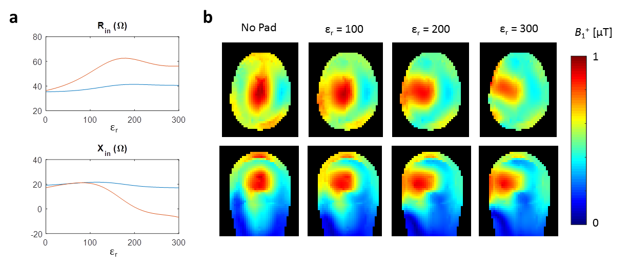
To illustrate the utility of the method we present two analyses of scenarios which involve a multiport coil model. The first is a 16-rung high-pass birdcage transmit coil, loaded by a male head model.6 A single dielectric pad of 18×18×1 cm3 is positioned on the left side of the head. Figure 1 shows the B1+ field generated by a port in close vicinity to the dielectric pad, and illustrates the accuracy of the domain decomposition procedure. The resulting fields are then combined in the circuit domain to quadrature mode as shown in Fig. 2. The time required to evaluate the field perturbation and circuit-level combination was 20 s, whereas re-evaluation of the 34 portwise fields via FDTD would have taken 38 minutes.
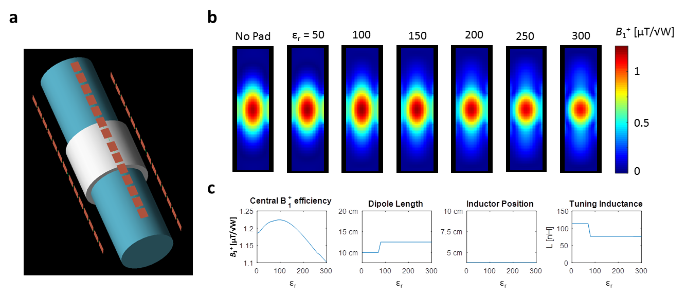
The second scenario concerns the parametric optimization of a four-channel dipole array surrounding a dielectric cylinder (εr = 60, σ = 0.65 S/m) with a centered dielectric sleeve of 10 cm length and 1-cm thickness (Fig. 3a). The aim is to maximize the central transmit efficiency by changing the permittivity of the sleeve in conjunction with the length of the dipole and the position of the tuning inductor. This is achieved by segmenting a 35-cm dipole into 2.5 cm sections and combining these in the circuit domain via a topological arrangement of shorts, opens and tuning inductors. The resulting parametric variation is shown in Fig. 3b and Fig. 3c and shows an optimal relative permittivity for the sleeve of 100. Solving for the action of the dielectric and running through the dipole design parameters in the circuit-domain took on average 35 s per value of the relative permittivity, compared to over an hour using FDTD.
Discussion and Conclusion
An efficient method to analyse the effects of a dielectric in coupled coil models has been demonstrated. By combining the domain decomposition method to account for the dielectric with a circuit-domain model of the coil, fast evaluations can be performed for arbitrary circuit arrangements as well as arbitrary dielectric shim designs. The method can be applied to any linearized coil model, such as transmit coil arrays as well as receive arrays in an analogous manner.Acknowledgements
This study has been supported by the Leiden University Fund / Nypels van der Zee Fonds.References
[1] Brink WM, Webb AG. High permittivity pads reduce specific absorption rate, improve B1 homogeneity, and increase contrast-to-noise ratio for functional cardiac MRI at 3T. Magn Reson Med 2014; 71:1632–1640.
[2] Collins CM, Carluccio G, Vaidya MV, et al. High-permittivity Materials can Improve Global Performance and Safety of Close-Fitting Arrays. Proceedings of the 22nd ISMRM in Milan, Italy, 2014; p. 404.
[3] Gemert JHF, Brink WM, Webb AG, Remis RF. An Efficient Methodology for the Analysis of Dielectric Shimming Materials in Magnetic Resonance Imaging. IEEE Trans Med Imag. 2016. DOI 10.1109/TMI.2016.2624507.
[4] Paska J, Froehlich J, Brunner DO, et al. Field Superposition Method for RF coil design. Proceedings of the 17th ISMRM in Honolulu, Hawaii, 2009; p. 3038.
[5] Beqiri A, Hand JW, Hajnal JV, et al. Comparison between Simulated Decoupling Regimes for Specific Absorption Rate Prediction in Parallel Transmit MRI. Magn Res Med 2015; 74:1423-1434.
[6] Christ A, Kainz W, Hahn EG, et al. The virtual family–development of surface-based anatomical models of two adults and two children for dosimetric simulations. Phys Med Biol 2010; 55:N23–N38.
Figures