4424
Fast 3D Design of High-Permittivity Pads for Dielectric Shimming using Model Order Reduction and Nonlinear Optimization1Circuits and Systems, Delft University of Technology, Delft, Netherlands, 2Radiology, Leiden University Medical Center, Leiden, Netherlands
Synopsis
High-permittivity pads can be used to improve B1+ homogeneity and intensity in neuroimaging and body applications. Normally, finding the “optimal” pad for a specific region of interest involves evaluating many different pad designs using electromagnetic simulations, which is a very time-consuming approach taking hours to days of computation time. We propose a nonlinear optimization method based on model order reduction that allows us to design high-permittivity pads in less than 30 seconds.
Purpose
Analyzing high-permittivity pads to improve B1+ homogeneity and intensity is normally accomplished by using full-wave solvers.1 The “optimal” design is found by evaluating a large number of pad realizations, typically, covering only a subset of the design parameters such as the permittivity, dimension, and location of the pad.2,3 This optimization process is computationally intensive, taking hours or even days to complete. We have shown previously that the process of evaluating such pad realizations can be accelerated by means of domain decomposition.4 This decomposition allows us to generate a pad-independent library for a pad design domain into which the dielectric pad can subsequently be positioned. In the current work we present further speed improvements by compressing this library significantly, such that the optimal pad can be found within 30 seconds using nonlinear optimization techniques.Methods
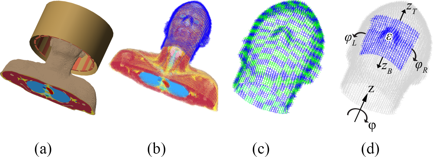
A spatial resolution of 5 mm3 is used for modeling the human head and corresponding RF fields for a 7T (298 MHz) neuroimaging application. The virtual family member “Duke” is used as body model5 combined with a 16-rung high-pass birdcage coil as shown in Figure 1(a). For the domain decomposition we consider a 1 cm thick pad design domain surrounding the head, as shown in Figure 1(b). Computations are performed with Remcom XFdtd (v.7.5.0.3) and Matlab (R2014b) on a Windows 64-bit machine (Intel Xeon CPU X5660@2.80 GHz, 48 GB memory, two NVIDIA Tesla K40c GPU’s).
Since we do not need a 5 mm3 resolution for designing dielectric pads, we artificially decrease the resolution by subdividing the pad design domain into 400 subdomains of approximately 2×2×1 cm3 as is shown in Figure 1(c). We then parameterize the design domain to model a rectangular pad with a single permittivity by using a superposition of Heaviside step functions. In such a way, we formulate the design problem as an optimization of five variables only, as illustrated in Figure 1(d).
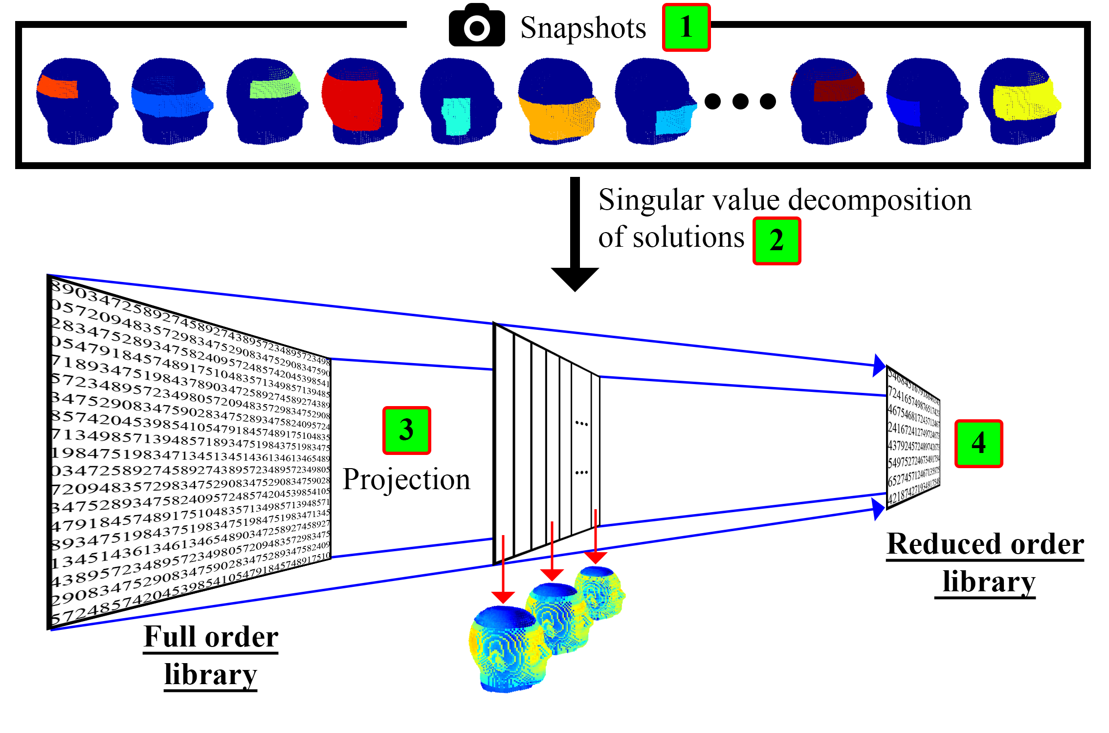
Within the range of pads that can be generated using this parameterization and subdomains, we can now compress the size of the original full order library by dispensing with information that does not contribute to the associated range of B1+ solutions. This compression is obtained by evaluating a series of pad realizations or “snapshots” where randomized values are assigned to our five design parameters. The resulting electric current density in the pad design domain is stored for each realization. Hereafter, the 500 most significant contributions are extracted by using a singular value decomposition, which forms a projection matrix.6 Finally, we project the library using this projection matrix on a new reduced order library giving us a Reduced Order Model (ROM). This process is illustrated in Figure 2.
For the optimization we define a cost function that is to be minimized as
$$C(\boldsymbol{p})=\frac{\lVert \boldsymbol{b}_1^+(\boldsymbol{p})- \boldsymbol{b}_1^{+\text{;desired}} \rVert^2_2}{\lVert \boldsymbol{b}_1^{+\text{;desired}} \rVert^2_2}$$
where $$$\boldsymbol{b}_1^+(\boldsymbol{p})$$$ is the B1+ field computed by the ROM and $$$\boldsymbol{b}_1^{+\text{;desired}}$$$ is the desired B1+ field intensity which is set to 1.2 µT. Finally, vector $$$p$$$ contains the parameters of the pad. The nonlinear optimization problem is solved using a Gauss-Newton algorithm combined with backtracking line search to determine the stepsize.
The optimized pads have been implemented using a stabilized suspension of barium and calcium titanate7 such that the B1+ maps can be compared with measured data obtained in vivo using a DREAM B1+ mapping sequence.8
Results
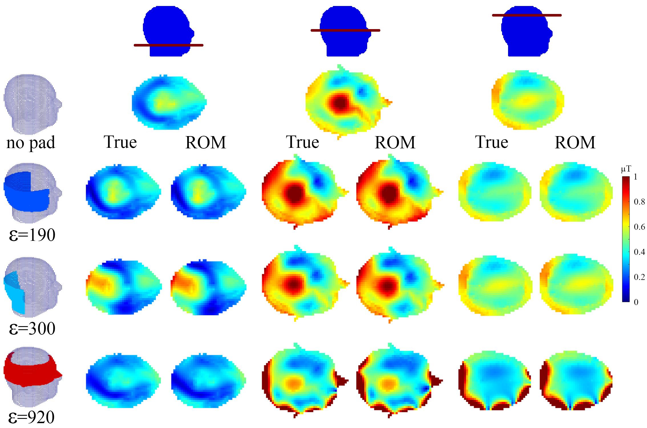
The model order reduction procedure compresses the library for the pad design domain, from 29 GB to 1 GB. Evaluating the B1+ field using the full order model completes in about 90 seconds when using GMRES (tolerance=10-4), whereas the ROM completes in 0.35 seconds when using a direct solver (≈250x speedup). A comparison of the B1+ fields for different dielectric pads obtained using the full order model and ROM is shown in Figure 3, where the global error in B1+ magnitude is around 5%.
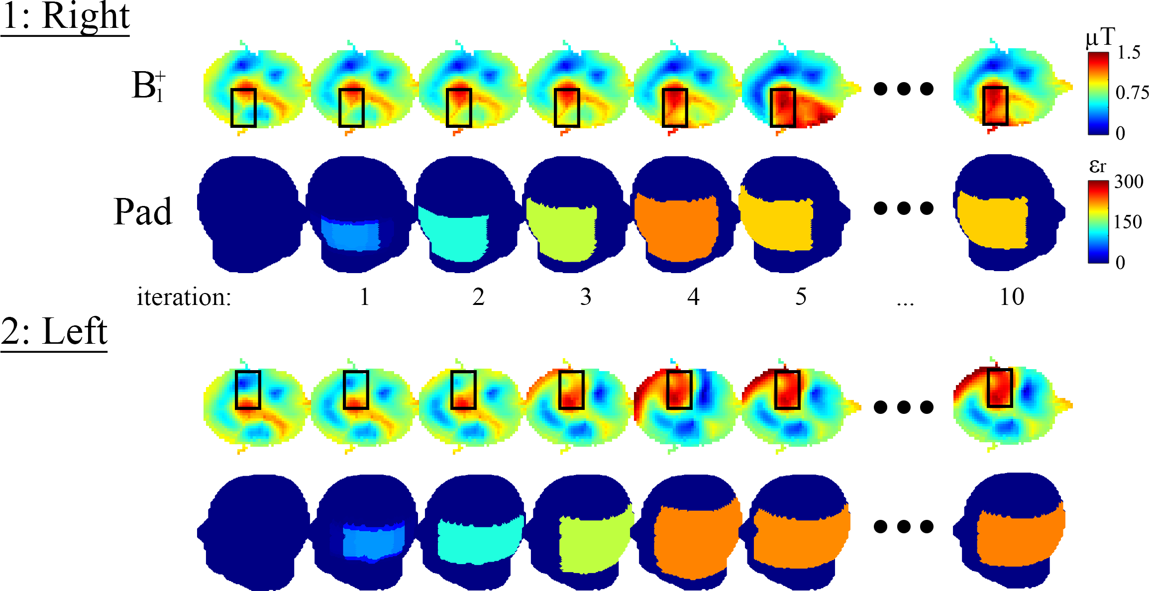
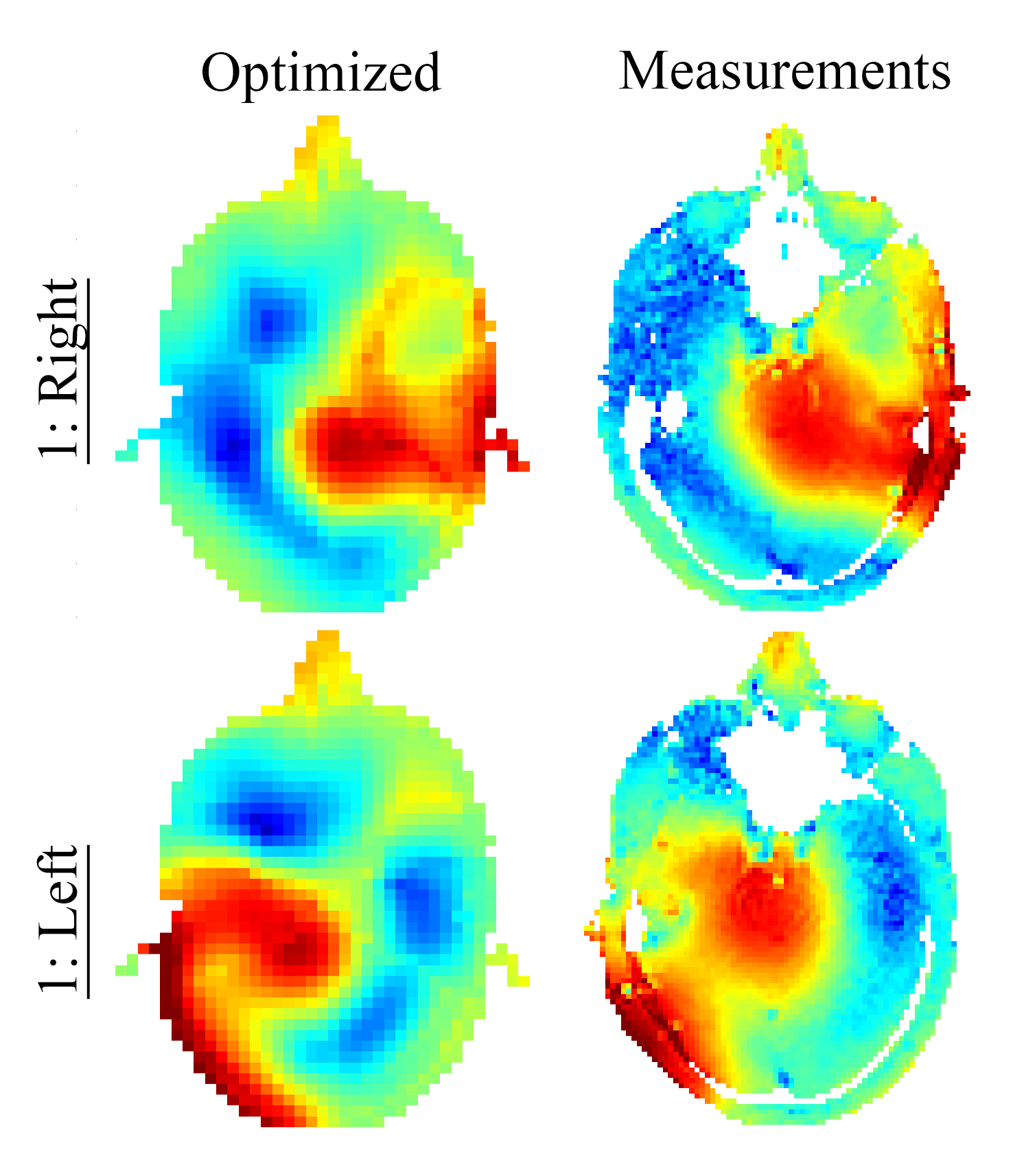
The evolution of the optimization method for two scenarios is shown in Figure 4, where the region of interests are indicated by black squares. Within 10 iterations and 30 seconds the method converges to a dielectric pad with a relative permittivity of 200 and 220, respectively, with corresponding dimensions of 13×16×1 cm3 and 13×22×1 cm3. The in vivo results are in good agreement as shown in Figure 5.
Discussion and conclusion
Practical dielectric pads can be designed in 3D within 30 seconds using the parameterized ROM and the optimization scheme. With the ROM, the B1+ field in the entire head can be obtained in 0.35 seconds for any dielectric pad. This approach can facilitate efficient 3D design of high-permittivity pads for dielectric shimming in high-field MRI.Acknowledgements
This research was funded by the Nederlandse Organisatie voor Wetenschappelijk Onderzoek (NWO), STW Project #13375.References
[1] Yang QX, Wang J, Collins CM, et al, Reducing SAR and enhancing cerebral signal-to-noise ratio with high permittivity padding at 3 T. Magn Reson Med. 2011;65(2):358-362.
[2] Brink WM, Webb AG. High permittivity pads reduce specific absorption rate, improve B1 homogeneity, and increase contrast-to-noise ratio for functional cardiac MRI at 3 T. Magn Reson Med. 2014;71(4):1632-1640.
[3] Teeuwisse WM, Brink WM, Haines KN, Webb AG. Simulations of high permittivity materials for 7 T neuroimaging and evaluation of a new barium titanate-based dielectric. Magn Reson Med. 2012;67(4):912-918.
[4] Gemert JHF, Brink WM, Webb AG, Remis RF. An Efficient Methodology for the Analysis of Dielectric Shimming Materials in Magnetic Resonance Imaging. IEEE Trans Med Imag. 2016. DOI 10.1109/TMI.2016.2624507.
[5] Christ A. The Virtual Family development of surface-based anatomical models of two adults and two children for dosimetric simulations. Phys. Med. Biol. 2010;55(2):23-28.
[6] Quarteroni A, Gianluigi R. Reduced Order Methods for Modeling and Computational Reduction. Vol. 9. Ch. 2. Springer, 2014.
[7] O’Reilly TPA, Webb AG, Brink WM. Practical improvements in the design of high permittivity pads for dielectric shimming in neuroimaging at 7T. J Magn Reson. 2016;270:108-114.
[8] Nehrke K, Börnert P. DREAM-A Novel Approach for Robust, Ultrafast, Multislice B1 Mapping. Magn Reson Med 2012;68:1517–1526.
Figures