4423
EKG-based detection of deep brain stimulation (DBS) for fMRI studies1GE Global Research Center, Niskayuna, NY, United States, 2Albany Medical College, Albany, NY, United States, 3Medtronic, Minneapolis, MN, United States
Synopsis
A detector for measuring and predicting the on/off state of cycling deep brain stimulation (DBS) was developed and tested in 6 patients. 3-electrode EKG measurements, amplified by a commercial bio-amplifier, were used as input for a custom electronics box (e-box). The e-box transformed the DBS waveforms into transistor-transistor logic (TTL) pulses and recorded their timing. Following locking to each patient’s individual waveform, the e-box was shown to predict stimulation onset with an average absolute error of 112ms, 30 minutes after disconnecting from the patients. Using this detector, stimulation can be accurately synchronized to fMRI acquisitions.
Introduction
Deep brain stimulation (DBS) is increasingly used for treating movement and psychiatric disorders1; the understanding of how the brain responds to different stimulation parameters is, however, limited. Quantitative measurements of brain response could help optimize stimulation parameters for conditions such as dystonia or depression, for which no real-time feedback currently exists. The recent Medtronic label change, allowing patients with specific hardware to be imaged with their stimulation ON2, opens the door for quantitative feedback using fMRI. Although programming DBS stimulation in an on/off cycling pattern is possible, the multi-second programmer-stimulator communication time and the 0.1-0.3s difference between the requested and measured stimulation periods can lead to multi-second errors in assessing the stimulation state; such errors can cause significant drops in fMRI sensitivity. In this work, a custom electronics box (e-box) is presented; used in conjunction with a standard 3-electrode EKG setup, it can determine the DBS timing and periodicity for each individual patient. An average absolute error of 112ms in predicting stimulation onset, 30min after ceasing direct measurements, is demonstrated in patients by our setup.Methods
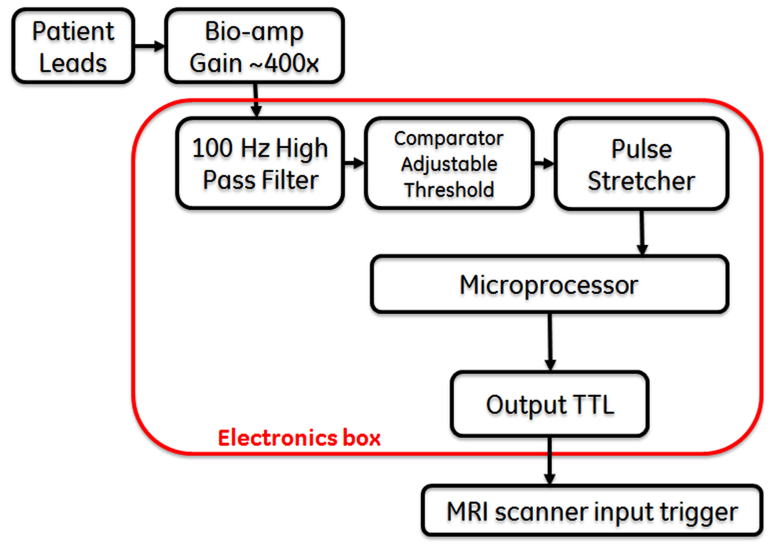
Figure 1 demonstrates the concept of operation for our device and its workflow; a standard 3-EKG-lead setup (forehead, near the DBS generator, abdomen) is used in conjunction with a commercial bio-amplifier for DBS signal detection and amplification. The operations performed by the e-box on the incoming signal include high pass filtering, TTL signal conversion through a comparator circuit with an adjustable threshold and pulse stretching (Figure 2). A microprocessor records the pulse timing in real time and calculates the period by averaging multiple cycles. Once a number of pulses (within a desired tolerance) are measured, a lock light turns on, and the EKG leads can be disconnected from the patient. The box can then be connected to the scanner external trigger input; its program prospectively propagates the measured period, continuously setting the output signal to match the DBS state. The patient can walk in the MRI scanner without any additional hardware; once the fMRI sequence is armed, the first ON trigger from the e-box will start the fMRI scan.
Six patients were studied with this paradigm under an IRB approved protocol. Once the e-box locked to the individual patient’s stimulation waveform, 3 patients were immediately disconnected, then reconnected after 30min; the remaining 3 subjects remained continuously connected for 30min. The measure of success for our detection scheme was the time-difference between the predicted and measured stimulation state over the time of scale of an fMRI exam (30min). Signals from patients with both unipolar and bipolar stimulation were initially examined, to assess detectability; due to the increased difficulty of the bipolar mode, and the fact that it is the only type of stimulation permitted during a MRI scan, only bipolar stimulation was included in the 30min evaluation.
Results and Discussion
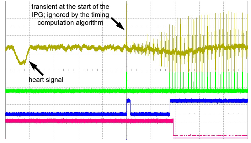
Figure 3 illustrates the raw signal measured in a patient, with one lead in unipolar mode (large signal) and one in bipolar mode (red arrows); although lower, the signals in bipolar mode are still detectable at sufficient signal to noise ratio (SNR). Figure 4 shows the start of a DBS pulse cycle, by displaying the input raw signal, the stretched TTL pulses, the pulse envelope, and the predicted output signal (driven to a low state when the DBS pulses are active) after locking. This patient had both leads in bipolar mode; the 2-level signals reflect the different distance between the EKG electrode and the two DBS leads.
Figure 5 (top) presents an example the difference between the predicted and actual stimulation state as a function of time; the non-linear error short term is likely explained by the limited SNR, as individual initial or final pulses in a train may exceed (or not) the detection threshold in a given cycle. Figure 5 (bottom) summarizes the characteristics and performance of our detector for all the patients included in the study. Note consistent performance across a wide range of parameters (voltage, frequency, cycling period, etc); the average absolute difference between the actual and predicted stimulation onset was 112ms. Note that the higher SNR of the unipolar DBS signals should make their detection significantly easier, and the prediction more accurate.
Conclusions
An approach for measuring and predicting the state of cycled DBS stimulation was developed for fMRI. An average 112ms error between the actual and predicted stimulation onset, 30min after disconnecting from the patient, allows for accurate stimulus/baseline assignment in fMRI paradigms. This scheme avoids real-time DBS measurements during MRI exams, when gradient induced noise may make direct DBS signal measurements difficult or impossible.Acknowledgements
No acknowledgement found.References
[1] State of the Art for Deep Brain Stimulation Therapy in Movement Disorders: A Clinical and Technological Perspective., Wagle Shukla A, Okun MS., IEEE Rev Biomed Eng. 2016;9:219-33
[2] http://manuals.medtronic.com/wcm/groups/mdtcom_sg/@emanuals/@era/@neuro/documents/documents/contrib_228155.pdf
Figures
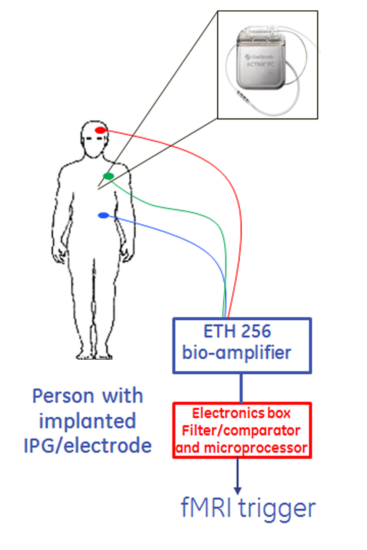
Figure 1: Schematic for EKG-based DBS detector. To avoid hardware addition in the MRI environment, our envisioned workflow involves:
1. Connecting EKG electrodes to each patient, outside of the MRI scanner
2. Determining precise timing of the DBS stimulation and “lock” to each individual patient excitation
3. Disconnecting everything from the patient; patient walks in the scanner for the start of the MRI exam
4. When ready for the start of the MRI exam, the electronics box has the memory of the ON/OFF state of the DBS excitation, and can trigger MRI scan at the beginning of the ON period.