4421
Improving Image Quality by Adjusting Relative Phases of Channels with a Two-element Rotating Coil Array at 9.4T1School of Information Technology and Electrical Engineering, The University of Queensland, Brisbane, Australia, 2Centre for Advanced Imaging, The University of Queensland, Brisbane, Australia, 3Bruker BioSpin MRI GmbH, Ettlingen, Germany
Synopsis
This work investigates the feasibility of incorporating an additional RF element to the rotating RF coil (RRFC) to improve imaging performance. The transmit profiles of the two-element rotating coil array were optimised by adjusting the interference patterns formed by two channels with varied relative phase. Combined with the previously developed rotating imaging scheme, an optimal relative phase was determined to produce an image uniformity of 93%.
Purpose
In high field MRI, the RF wavelength is usually comparable to the size of the imaged subject, giving rise to inhomogeneous excitation profiles. Coil arrays equipped with parallel and simultaneous channels have the ability to manipulate constructive and destructive interference patterns by adjusting the magnitudes and/or relative phases of the transmission signal, and thus the ability to homogenise the transmit field (B1+ ). The recently developed rotating RF coil (RRFC) has also demonstrated flexibility in providing uniform image recovery for a large volume with only one surface-type rotating RF element 1-4. In this work, we investigate the feasibility of adding an additional RF element to the RRFC, for the purpose of providing enhanced capability of tailoring transmit fields by means of interference construction between the two channels, thus producing uniform or tailored images.Methods
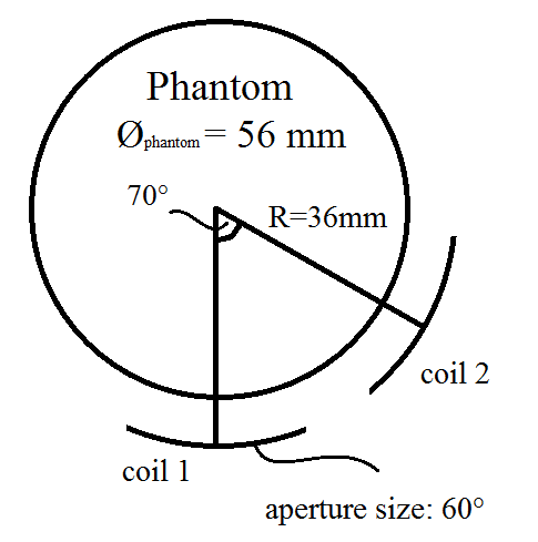
The proposed two-element rotating coil array consists of two inductively-decoupled coil elements with an aperture size of 60° and a longitudinal length of 60mm, positioned on a coil former of 72mm in diameter. A cylindrical phantom (Ø=56 mm, H=120mm) with a permittivity εr = 60 and conductivity σ = 0.55 was used in simulation. The top view of the coil/phantom geometry is displayed in Figure 1. The EM simulation was performed with FEKO (Hyperworks, USA), and Matlab (Massachusetts, USA) was used to process rotation-dependent transmit/receive sensitivity profiles 5. The image recovery method developed previously was employed 3. The transmission phase of the second channel was adjusted from -180° to 170° with 10° increment. In a practical application, the optimal phase difference and power splitting between two channels can be achieved using hybrid power splitters/combiners. The signal intensity of the image scales with the composite sensitivity profile |ΣB1+|·Σ|B1-| , provided the flip angle is small.Results
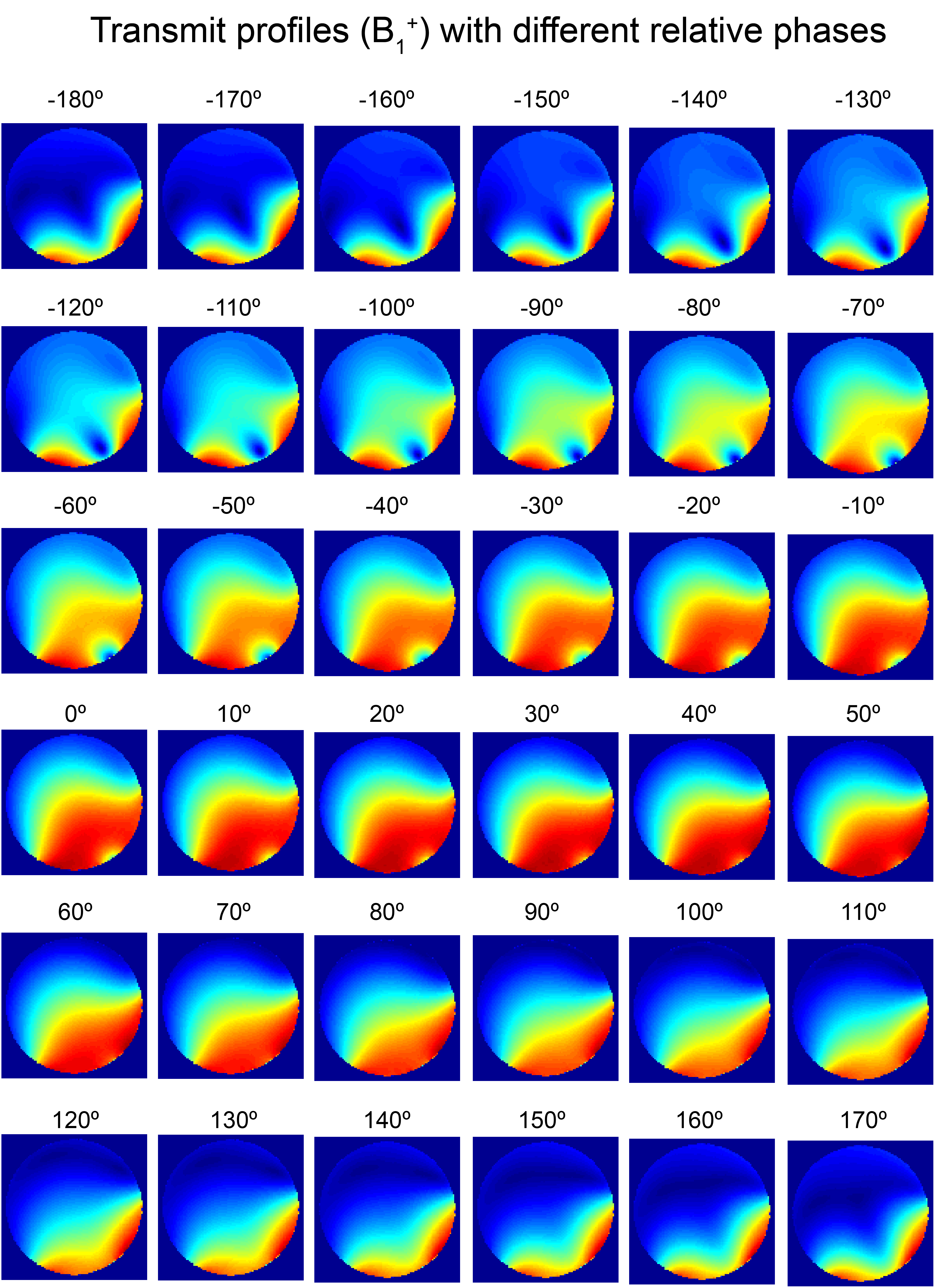
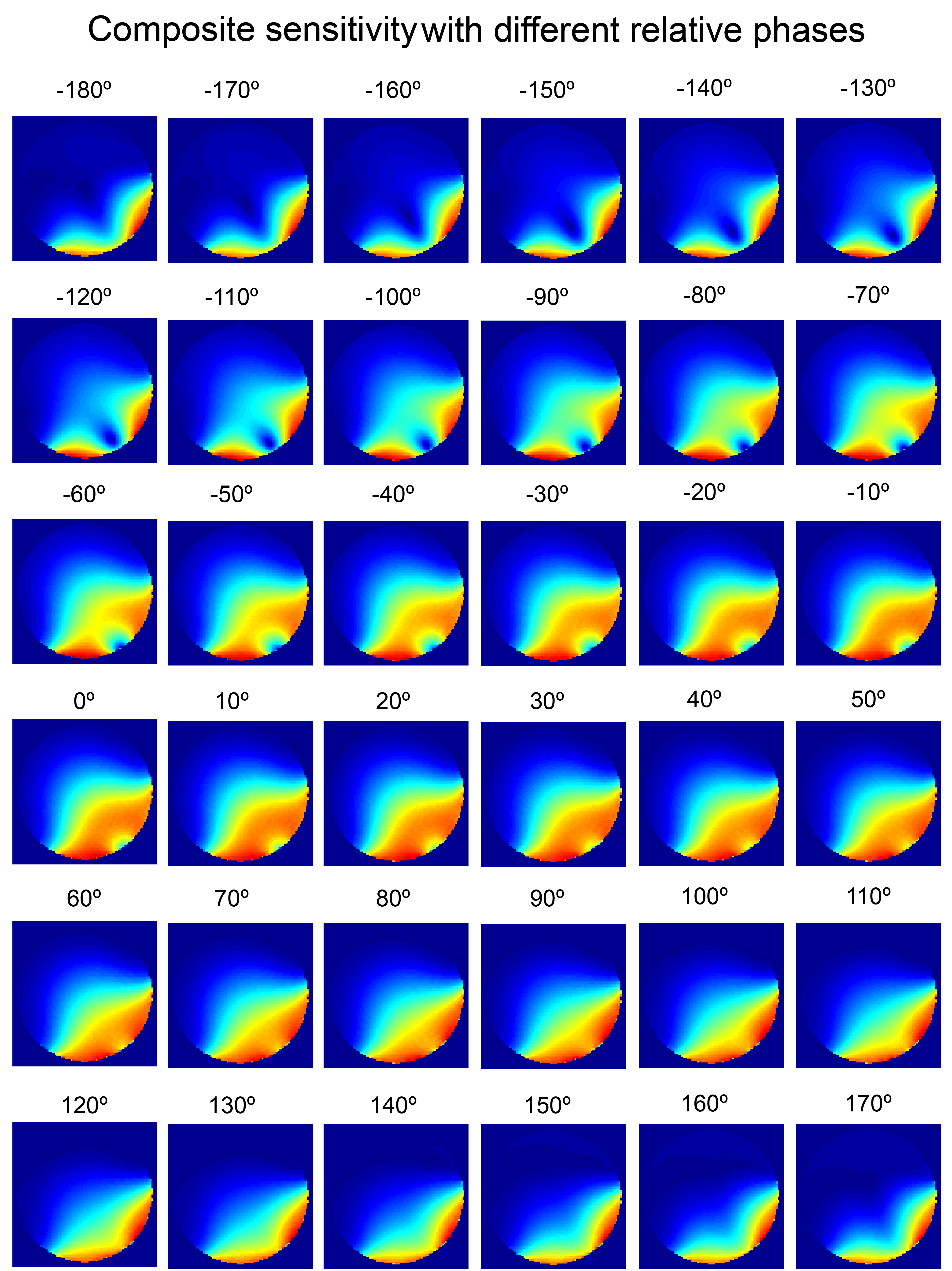
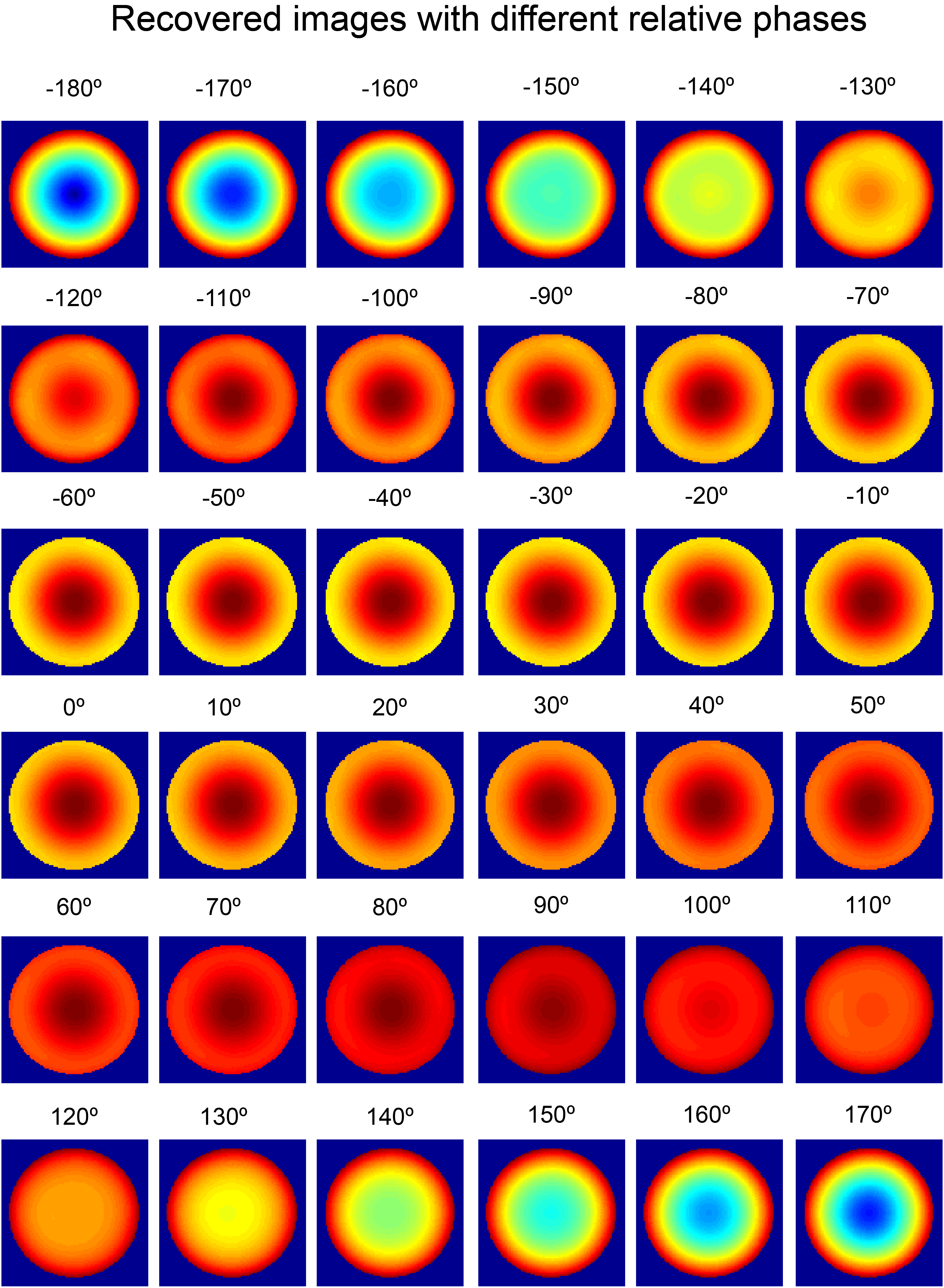
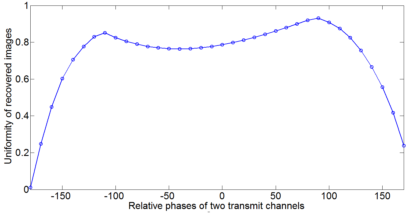
As shown in Figure 2, while the phase differences between two transmit elements were varied between -80° and 80°, the transmit profiles had better penetration at the centre of the phantom through the constructive interferences; however, this could also potentially reduce the image uniformity in the case of rotating array imaging. The composite sensitivity profiles in Figure 3 include the weightings of both transmit and receive sensitivities, which would directly correlate the image quality of the final recovered images in Figure 4. It is obvious that the dark band in Figure 3 caused signal drop in the peripheral regions while the phase differences are between 0° and -90°. However, the shallow penetration of the composite sensitivity in Figure 3 led to signal drop in the centre when the phase differences are between 130° and 170°, -140° and 180°. The uniformity of the recovered images with different relative phases is plotted in Figure 3. The best image uniformity (0.9315) was found when the phase difference was 90°.Discussion
The coil sensitivity is closely dependent to the coil geometry and coil/subject interaction. Two coils were positioned with 70° separation as shown in Figure 1, leaving enough space to insert decoupling elements. In addition, smaller distances between two coils will assist forming constructive interference and receive sensitivities of two coils will not have a dark band. With the current coil geometry, the optimal relative phase between the two transmit elements to produce the best image uniformity is approximately 90°. However, this optimal phase could be changed with different coil geometry. As shown in Figure 1, even with two RF elements fitted to the cylindrical former, adequate space is left on the rotary former which could be used to accommodate extra RF elements.Conclusion
In this work, we have demonstrated that the proposed two-element rotating coil array was capable of recovering images with uniform intensity, by adjusting transmit profiles through optimising the relative phases of two elements. The optimal phase difference between two coils was 90°. This two-element rotating coil array offers a unique ability to adjust transmit profile even without using expensive parallel transmission system. In future work, the proposed rotating coil array will be prototyped and various imaging protocols will be tested.Acknowledgements
This work was supported by the Australian Research Council Linkage Projects ( LP120200375).References
1.Trakic A, Li B, Weber E, Wang H, Wilson S, and Crozier S, A rapidly rotating RF coil for MRI, Concepts in Magnetic Resonance Part B: Magnetic Resonance Engineering, 2009, V35B, 59-66
2.Trakic A, Wang H, Weber E, Li B, Poole M, Liu F and Crozier S, Image reconstructions with the rotating RF coil, Journal of Magnetic Resonance, 2009, V201, 186-198
3.Li M, Hugger T, Weber E, Jin J, Liu F, Ullmann P, Stark S, Tesiram Y, Yang Y, Junge S, and Crozier S, A Fast and Practical Imaging Scheme for a Rotating RF Coil at 9.4T by Using Ultra-short TE Sequence in Radial Trajectory, in proceeding International Society for Magnetic Resonance in Medicine, 21th scientific meeting and exhibition, 2015, Toronto, Canada
4.Trakic A, Jin J, Li M, McClymont D, Weber E, Liu F and Crozier S, A comparative numerical study of rotating and stationary RF coils in terms of flip angle and specific absorption rate for 7 T MRI, Journal of Magnetic Resonance, 2009, V236 70-82.
5.Hould D, The principle of reciprocity in signal strength calculations—A mathematical guide, Concepts in Magnetic Resonance Part A, 2000, V12, 173-187
Figures