4420
A new RF coil for foot and ankle imaging at 7T MRI1University of Pittsburgh, Pittsburgh, PA, United States
Synopsis
7T Foot and ankle has been previously explored1. A four-channel Tic-Tac-Toe (TTT) transmit-only (Tx-only) array2,3 and a four-channel receive-only array were developed and combined to demonstrate the
Purpose
To design an RF coil system to be used for ankle and foot imaging at 7T.Methods
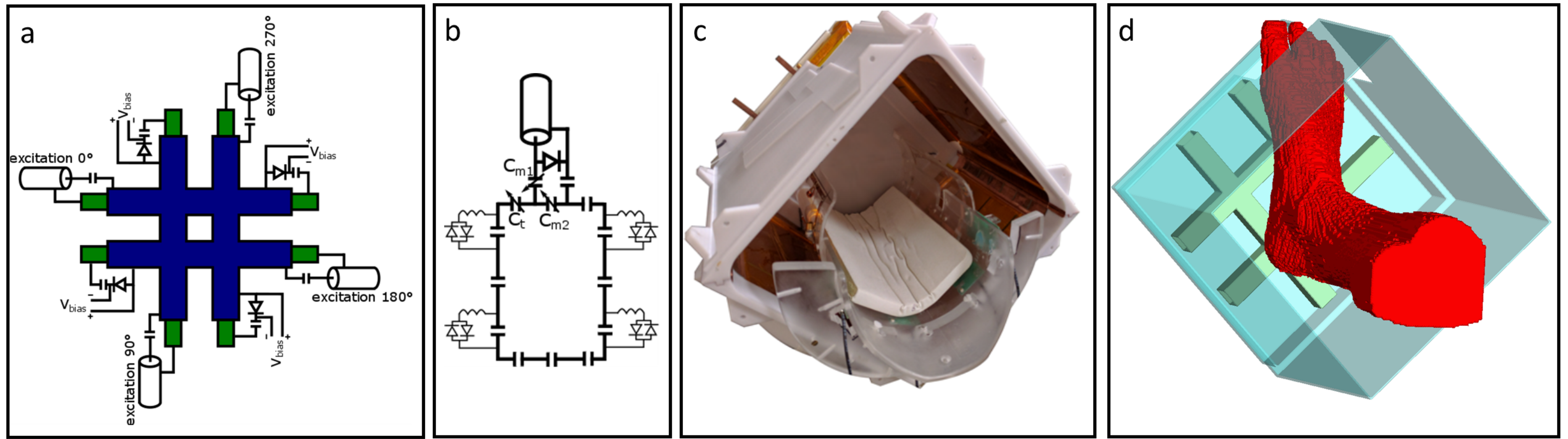
A four-channel transmit-only (Tx-only) Tic-Tac-Toe (TTT) RF coil was designed based on cross-pole antenna structure4 to be used for foot and ankle imaging. The 2x2 TTT coil is composed of 8 transmission lines, with 8 outer struts (represented in blue in the Figure 1a) and 8 inner metal rods (in green in Figure 1a) where 4 rods are used for tuning and other 4 rods are used for matching. Double layered copper shields cover the entire inner part of the coil, with exception to a portion that was cut at the top of the coil to accommodate the toes (see Figures 1c and 1d). The copper shields are designed with several cuts to suppress eddy currents while maintaining the RF coil characterisitcs3. The coil operates in pseudo-circular polarized (CP) mode (90 degree excitation phase increment in clockwise rotation with equal input voltage, using a 4-way Wilkinson power splitter), and it is positioned close to the bottom of the foot in the XY (transverse) plane of the magnet (Figures 1c and 1d).
For the signal reception, a four-channel receive-only loop coil was built and positioned around the foot and ankle. This configuration partially alleviates image inhomogeneities (due to B1+) and improves the signal-to-noise ratio (SNR). An active decoupling circuit was mounted on both the Tx-only and Rx-only arrays (Figure 1a and 1b), and the Rx-only array also contained passive decoupling (Figure 1b).
A full-wave simulation was performed using an in-house FDTD software with an accurate transmission line feed model. An FDTD grid (resolution of 0.16mm isotropic) was generated using Matlab (Natick, MA) and the foot and lower leg of the anatomical model were extracted from the Duke virtual family (Figure 1b). B1+ and SAR were calculated from the simulation results using Matlab.
The developed RF coil (transmit and receive) was tested using a 7T MRI scanner (Siemens, Erlangen, Germany). The images were acquired in a healthy volunteer. B1+ maps were acquired at 3.2mm3 isotropic resolution using the saturated turbo FLASH method, with scan time of 6min. Proton density 2D turbo spin echo (TSE) images were acquired at 0.4x0.4x1.5mm, sagittal slices, with TE/TR/TA = 24ms/3000ms/5min. 3D T2-weighted dual echo steady state (T2DESS) were acquired at a resolution of 0.6mm isotropic, with TE/TR/TA = 5ms/20ms/9min. Only standard product sequences were used and no post-processing was performed.
Results
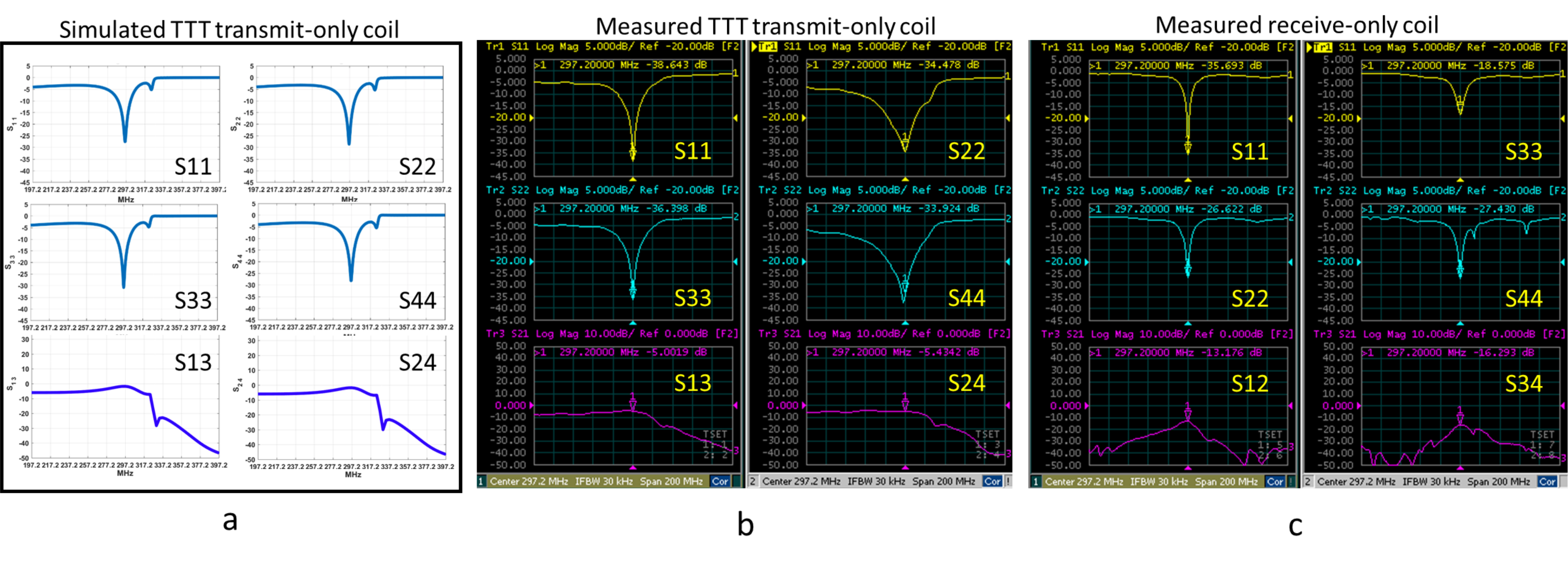
The scattering parameters of the TTT Tx-only array are shown in the Figures 2a (simulated) and 2b (measured). An average value of was observed for the reflection coefficient (S11), while the average coupling between opposite ports (S13) was (intentionally elevated based on the design of this coil). Figure 2c shows the scattering parameters measured in the receive-only array. The average reflection coefficient was and the coupling between consecutive loops was on average. All measurements were performed using a human foot as the load.
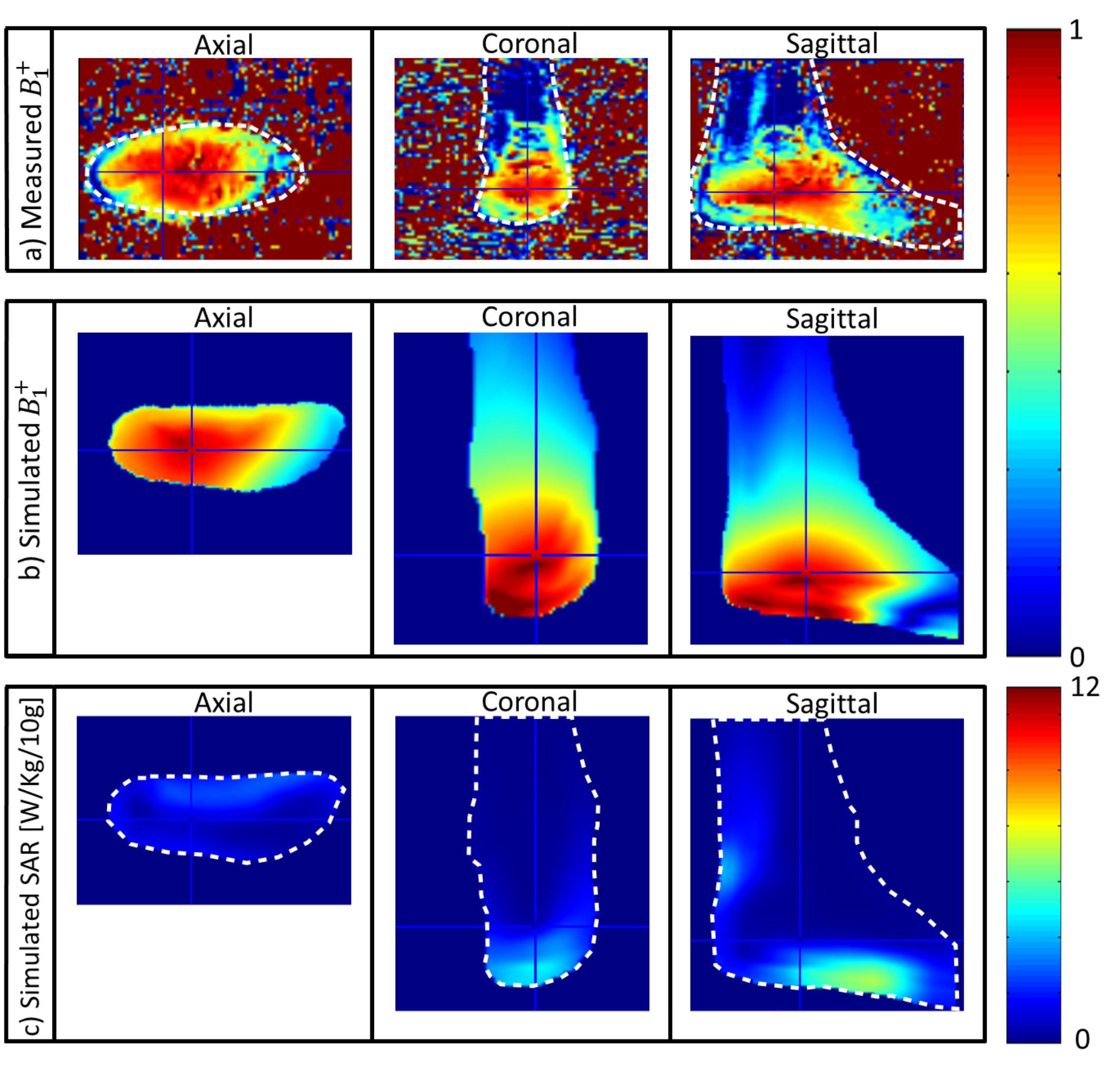
Figure 3a shows the B1+ maps measured in a subject. B1+ map measurement is particularly challenging in the volume of interest (ankle and foot) due to the presence of bone. Figures 3b and 3c present the simulated B1+ and the respective SAR maps. The average SAR observed was 1.03W/kg per 10g of tissue, while the peak SAR was 7W/kg/10g of tissue.
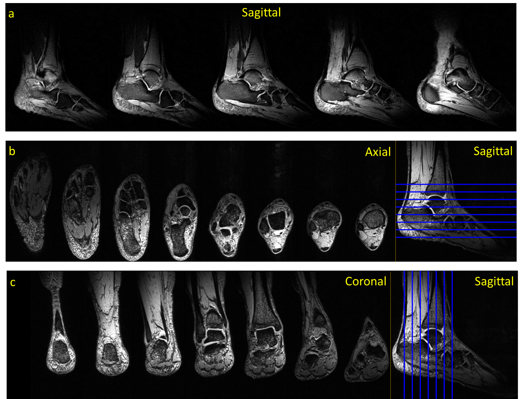
Proton density foot/ankle images were acquired using TSE in sagittal plane (Figure 4A). 3D T2DESS was also used to acquire foot/ankle images and the transverse and coronal planes are shown in Figures 4b and 4c.
Discussions and conclusion
The results demonstrate the feasibility of the Tic-Tac-Toe design for foot and ankle imaging at 7T. The transmit-only coil is positioned in the XY and produces a magnetic field that extends in Z-direction from its center. The foot can be repositioned according to the region of interest for the acquisition and for the comfort of the subject. Our developed RF array was capable of running a TSE sequences which is power demanding and sensitive for B1+ field inhomogeneity. While we used pseudo-CP mode for transmission, the RF array allows for RF shimming and further improvement in achieving a specified B1+ field distribution. Simulation data show that the effect of creating a cavity (in order to allow for the toe region) on characteristics of RF coil was negligible (not shown).Acknowledgements
This work was supported by NIHReferences
1 Orzada, S., Bitz, A. K., Schafer, L. C., Ladd, S. C., Ladd, M. E., & Maderwald, S. (2011). Open design eight-channel transmit/receive coil for high-resolution and real-time ankle imaging at 7 T. Med Phys, 38(3), 1162-1167. doi:10.1118/1.3553399
2 Kim, J., Krishnamurthy, N., Santini, T., Zhao, Y., Zhao, T., Bae, K. T., & Ibrahim, T. S. (2016). Experimental and numerical analysis of B1+ field and SAR with a new transmit array design for 7T breast MRI. J Magn Reson, 269, 55-64. doi:10.1016/j.jmr.2016.04.012
3 Zhao, Y., Zhao, T., Raval, S. B., Krishnamurthy, N., Zheng, H., Harris, C. T., . . . Ibrahim, T. S. (2014). Dual optimization method of radiofrequency and quasistatic field simulations for reduction of eddy currents generated on 7T radiofrequency coil shielding. Magnetic Resonance in Medicine.
4 Ibrahim, T. S., Hue, Y.-K., Boada, F. E., & Gilbert, R. (2008). Tic Tac Toe: Highly-Coupled, Load Insensitive Tx/Rx Array and a Quadrature Coil Without Lumped Capacitors. Paper presented at the Intl. Soc. Mag. Reson. Med.
Figures