4419
A method to experimentally assess “coil loss” of a dipole antenna for Ultra-High-Field (UHF) MRI1Center for Advanced Imaging Innovation and Research (CAI2R), New York University School of Medicine, New York, NY, United States, 2The Sackler Institute of Graduate Biomedical Science, New York University School of Medicine, New York, NY, United States
Synopsis
At clinical field strengths, the contribution of coil noise is often characterized by the Q-ratio, the ratio of the loaded Q and unloaded Q. Because of the inconsistent contribution of radiation loss and frequency drift in unloaded and loaded cases, it is difficult to characterize the body noise dominance of a dipole antenna by conventional Q ratio at 7T. Here we propose a new approach using a measure of Q when a dipole antenna is well shielded. The shielded/loaded Q ratio estimates the relative noise contribution from coil loss, similar to unloaded/loaded Q ratio for surface coil at low frequencies.
Purpose
At clinical field strengths, the contribution of coil noise is often characterized by the Q-ratio, the ratio of the Q of the coil in free space divided by the Q when it is placed next to the body. The noise attributed to coil losses can be given by [1] $$\frac{Coil noise}{Total noise} = \frac{ \sqrt{P_{coil} + P_{sample}} - \sqrt{P_{sample}}} {\sqrt{P_{coil}+P_{sample}}}\tag{1}$$ $$=1-\sqrt{1-(Q_{loaded}/Q_{unloaded})}\tag{2}$$Where $$$P_{coil}$$$ and $$$P_{sample}$$$ are power loss in the coil and sample respectively. However, at 7 tesla, radiation loss is dominant when a self-resonant dipole antenna is placed in free space [2], and diminishes when the dipole is heavily loaded by the sample [3]. Because of the inconsistent contribution of radiation loss and frequency drift in unloaded and loaded cases, it is difficult to characterize the body noise dominance of a dipole antenna by conventional Q ratio. Here we propose a new approach using a measure of Q of the dipole antenna when it is well shielded. Simulations and experiments were used to characterize the power budget of dipole antennas in a variety of configurations and to validate this new approach.
Theory
Shielding a dipole antenna greatly reduces radiation loss. The resonant frequency of the shielded dipole can be made to match that when it is loaded by adjusting the distance between the dipole and the shield. The noise attributed to coil losses can then be defined by replacing $$$Q_{unloaded}$$$ with $$$Q_{shielded}$$$ $$\frac{Coil noise}{Total noise} \approx 1-\sqrt{1-(Q_{loaded}/Q_{shielded})}\tag{3}$$Methods
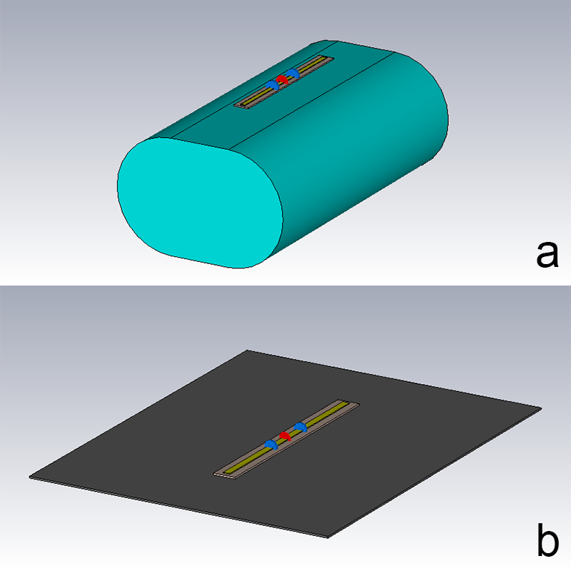
Finite Element Method (FEM) simulations were performed with Microwave studio (CST, Darmstadt, Germany). A 250 mm long inductor-shortened dipole antenna was modeled at various distances above a torso-shaped phantom (Figure 1a) having tissue-like properties ($$$\epsilon_{r}$$$ = 40.5,$$$\sigma$$$ = 0.58 S/m), and was tuned to 297.2 MHz in each case by adjusting the shortening inductors (modeled as lossy elements) [4]. For each case, the dipole was also simulated next to a conductive shield (Figure 1(b)), and was tuned to 297.2 MHz by adjusting the distance to the shield.
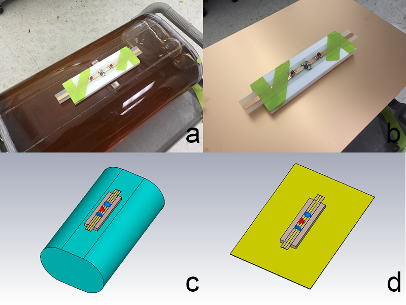
To validate the simulations, we built and tested a single dipole antenna prototype and compared experimentally measured and simulated characteristics. A horizontal 250 mm long inductor-shortened dipole antenna was constructed. When loaded with the torso shaped phantom as shown in Figure 2a, the dipole antenna was tuned to 297.2 MHz by adjusting the inductors. The same dipole was then placed above a copper shield and tuned to 297.2 MHz by only changing the distance to the shield (Figure 2b). Simulations were performed with similar configurations as the bench measurements (Figure 2c, 2d).
Results
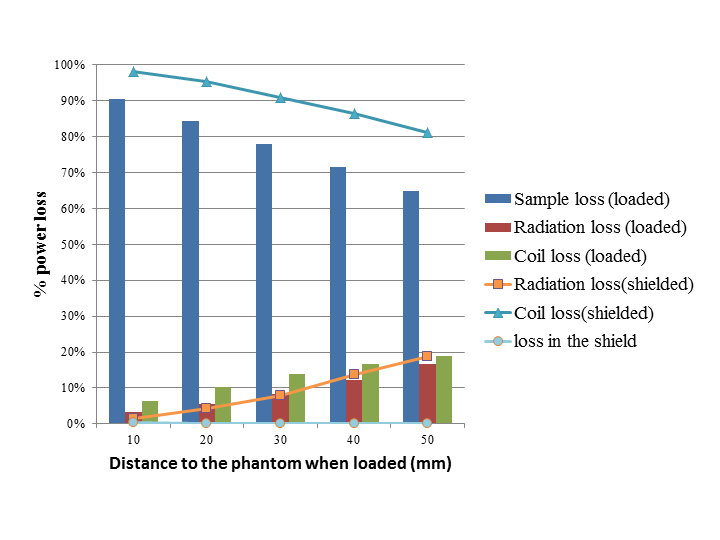
Figure 3 shows that sample loss is dominant when the dipole is well loaded by the phantom, and coil loss is dominant when the dipole is well shielded. The radiation loss provides similar contributions in both loaded and shielded configurations, and can thus be removed when taking the ratio $$$Q_{shielded}/Q_{loaded}$$$.
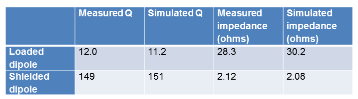
Table 1 shows the comparison of input impedance and Q factor between simulations and bench measurements. A shielded/loaded Q ratio of 12.6 (13.5 in the simulations) indicates that the phantom noise is dominant when the dipole is loaded. When the constructed dipole is in free space, the resonant frequency shifts from 297.2 MHz to 338.3 MHz, input impedance was 25.8 $$$\Omega$$$ and the Q factor was 19. Simulations show that radiation loss accounts for 95% of total power accepted by the dipole antenna when it is in free space. Because the radiation loss is dominant when the dipole is in free space, the unloaded/loaded Q ratio of 1.45 doesn’t estimate coil loss correctly. Using the information available in this last simulation we can show that the right-hand side (RHS) of equation (3), equal to 0.037, is much closer to the quantity these equations are intended to approximate, the RHS of equation (1), equal to 0.035, than is the RHS of equation (2), equal to 0.35.
Conclusion
We present an accurate and easy approach to characterize the body noise dominance of a dipole antenna at UHF: 1) Tune the dipole antenna when loaded with the phantom and measure the loaded Q factor. 2) Put the dipole above a conductive shield, adjust the height to get the desired frequency and measure the shielded Q factor. 3) Use the shielded/loaded Q ratio to estimate the relative noise contribution from coil loss, similar to unloaded/loaded Q ratio for surface coil at low frequencies. The proposed approach can applied to surface loop coils at UHF as well, and may not be accurate when the coil is lightly loaded by the sample.Acknowledgements
This work was supported by the Center for Advanced Imaging Innovation and Research (www.cai2r.net), a NIBIB Biomedical Technology Resource Center (NIH P41 EB017183).References
[1] Hayes CE, Axel L. Noise performance of surface coils for magnetic resonance imaging at 1.5 T. Med Phys 1985;12(5):604-7.
[2] Hansen PM. Radiation Efficiency of a Dipole Antenna Located above an Imperfectly Conducting Ground. Ieee Transactions on Antennas and Propagation 1972;Ap20(6):766-&.
[3] Raaijmakers AJ, Luijten PR, van den Berg CA. Dipole antennas for ultrahigh-field body imaging: a comparison with loop coils. NMR Biomed 2015.
[4] Chen G, Lattanzi R, Sodickson DK, Wiggins GC. Approaching the ultimate SNR with dense arrays of electric dipole antennas. Proc. ISMRM 2016; Singapore. p168.
Figures