4415
The TEM horn: A new array element for high-field imagingAtefeh Kordzadeh1 and Nicola De Zanche2
1Biomedical Engineering, University of Alberta, Edmonton, Canada, 2Medical Physics, University of Alberta, Canada
Synopsis
This abstract introduces the TEM horn antenna as an efficient element for imaging the human body at high fields. The horn was designed for 200.4 MHz, simulated in HFSS adjacent to a torso-size phantom, and fabricated using 3-D printing. Transmit/receive imaging measurements were performed at 4.7T. Flip angle maps are compared to the simulation results.
- Purpose
Developing radio frequency (RF) coils for high
field MRI is challenging because of higher RF frequencies than standard fields,
and thus shorter wavelengths [1], [2], [3]. Consequently, destructive and constructive
interference leads to dark and bright areas in the image, as well as to
specific absorption rate (SAR) hotspots. Penetration depth also decreases. In
recent years elements adapted from antennas have been introduced to high-field
MRI to mitigate these effects and improve efficiency at higher frequencies. For
example, dipoles have shown advantages over conventional loops especially for
deeper targets [4], [5]. Other designs consist mostly of variations of
the dipole antenna such as bowties [6] and combined loop-dipole elements [7]. This abstract introduces the TEM horn antenna
[8] as an efficient element for high-field imaging
(>3 T).- Methods
The horn antenna is shown in Figure 1 (a) and is
designed to image body regions at 4.7 T. It is fed using coaxial cable that
excites a parallel-plate waveguide, and is matched at 200.4 MHz. To
operate at this frequency both waveguide and horn sections are filled with
deionized water, and a 19-mm-thick water spacer is placed between horn and
phantom. The phantom is a 40×40×30 cm3 plastic container filled with
a solution (isopropyl alcohol, deionized water and sodium chloride) to mimic
the average electrical properties of the body (εr=34, σ=0.4 S/m) [9]. The horn is
simulated using High
Frequency Structure Simulator (HFSS V.15, Ansys, USA) in the presence of the
phantom and fabricated as a hollow 3-D printed acrylic
(PMMA) watertight container. Scattering parameters were measured on the bench
using an Agilent 4395A VNA. Images were acquired on a 4.7 T whole-body MRI
system (Unity Inova; Varian, Palo Alto, California). The acquisition parameters are TE=7 ms, TR=1000 ms
or longer, 420×420×300 mm FOV and 2 × 2
× 10 mm resolution. - Results
Figure 1
(b) shows the measured S11 of the antenna in presence of the load
showing excellent tune and match (-20dB) at 200MHz. The simulated average sensitivity
of the coil (B1+/√W) is 0.056 µT/√W
which compares
favorably to that of a dipole (0.050 µT/√W ) . Figure
2 (a) and (b) show the simulated B1+ field for coronal and
sagittal slices respectively. The coronal plane is located at a depth of 5 cm
from the antenna aperture. The B1+ field on the sagittal
slice show the significant penetrating depth of the B1+
field of the proposed antenna. Acquired signal in coronal and sagittal slices are
shown in Figure 3 (a) and (b) respectively. The acquired images are consistent
with the simulation results. Conclusion
The proposed pyramid horn shows promising ability to image deep body targets at high fields. It is readily fabricated and with this setup has not required laborious tuning and matching. Future work includes assembling multiple TEM horns into an array to measure coupling and perform imaging in vivo. The horn and spacer will be filled with D2O to eliminate the corresponding signal.Acknowledgements
The authors gratefully acknowledge funding from the Natural Sciences and Engineering Research Council (Canada) and thank Messrs. Karim Damji and Peter Šereš for assistance with the MRI measurements. We acknowledge Dancam Design and Mr. Ken Hennig for helping in fabrication. Software access through the Canadian Microelectronics Corporation, and scholarships from the University of Alberta are also acknowledged.References
[1] K. J. Chang and I. R. Kamel, “Abdominal imaging at 3T: Challenges and solutions,” Appl. Radiol., vol. 39, no. 10, 2010. [2] L. B. Pierre-Marie Robitaille, "Ultra High Field Magnetic Resonance Imaging", Volume 26 of Biological Magnetic Resonance, vol. 1. Springer US, 2006, 2006. [3] J. Thomas Vaughan, J. R. Griffiths, "RF coils for MRI". John Wiley & Sons, Inc., 2012. [4] A. J. E. Raaijmakers, O. Ipek, D. W. J. Klomp, C. Possanzini, P. R. Harvey, J. J. W. Lagendijk, and C. A. T. Van Den Berg, “Design of a radiative surface coil array element at 7 T: The single-side adapted dipole antenna,” Magn. Reson. Med., vol. 66, no. 5, pp. 1488–1497, 2011. [5] A. J. E. Raaijmakers, P. R. Luijten, and C. A. T. van den Berg, “Dipole antennas for ultrahigh-field body imaging: a comparison with loop coils.,” NMR Biomed., no. April, 2016. [6] L. Winter, C. Ozerdem, W. Hoffmann, D. Santoro, A. MUller, H. Waiczies, R. Seemann, A. Graessl, P. Wust, and T. Niendorf, “Design and Evaluation of a Hybrid Radiofrequency Applicator for Magnetic Resonance Imaging and RF Induced Hyperthermia: Electromagnetic Field Simulations up to 14.0 Tesla and Proof-of-Concept at 7.0 Tesla,” PLoS One, vol. 8, no. 4, 2013. [7] M. A. Ertürk, A. J. E. Raaijmakers, G. Adriany, K. Ugurbil, and G. J. Metzger, “A 16-channel combined loop-dipole transceiver array for 7 Tesla body MRI,” Magn. Reson. Med., vol. 00, pp. 1–11, 2016. [8] D. Oloumi, P. Mousavi, M. I. Pettersson, and D. G. Elliott, “A Modified TEM Horn Antenna Customized for Oil Well Monitoring Applications,” IEEE Trans. Antennas Propag., vol. 61, no. 12, pp. 5902–5909, Dec. 2013. [9] B. Van Den Bergen, C. A. T. Van Den Berg, D. W. J. Klomp, and J. J. W. Lagendijk, “SAR and power implications of different RF shimming strategies in the pelvis for 7T MRI,” J. Magn. Reson. Imaging, vol. 30, no. 1, pp. 194–202, 2009.Figures
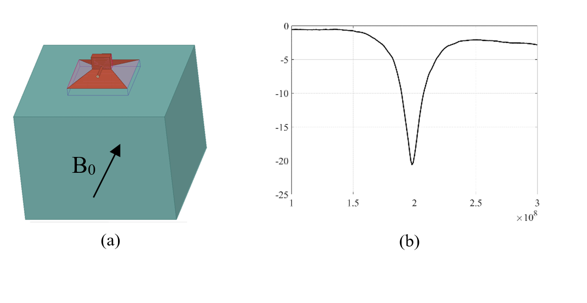
(a)
Structure of the RF horn element and parallel-plate waveguide feed; (b) measured
S11.
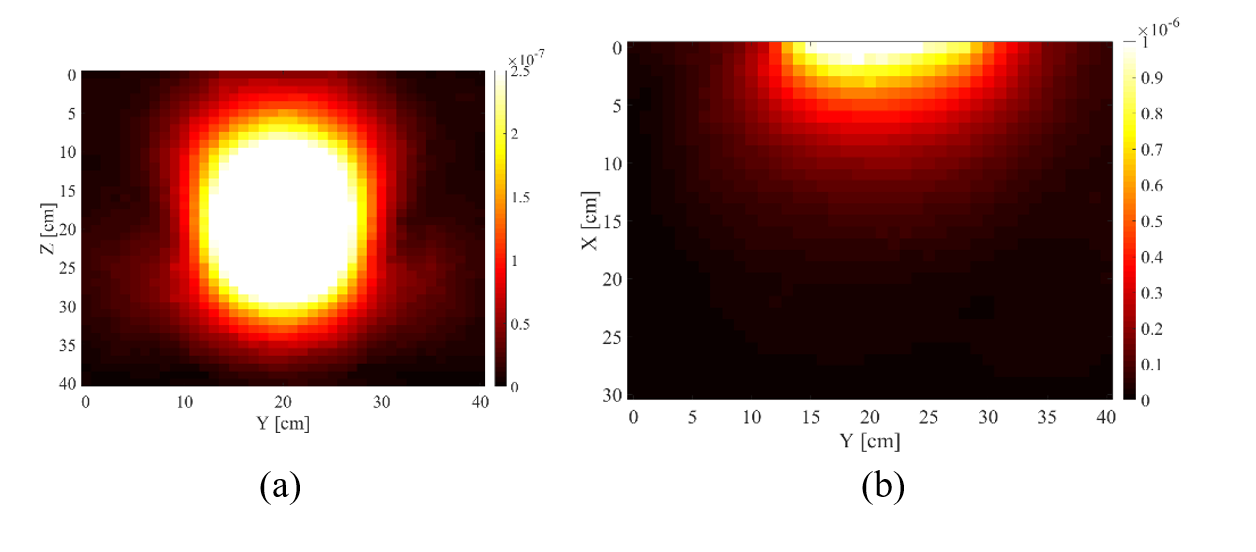
Simulated B1+ field
(a) on a coronal plane 5 cm below the antenna, (b) sagittal slice.
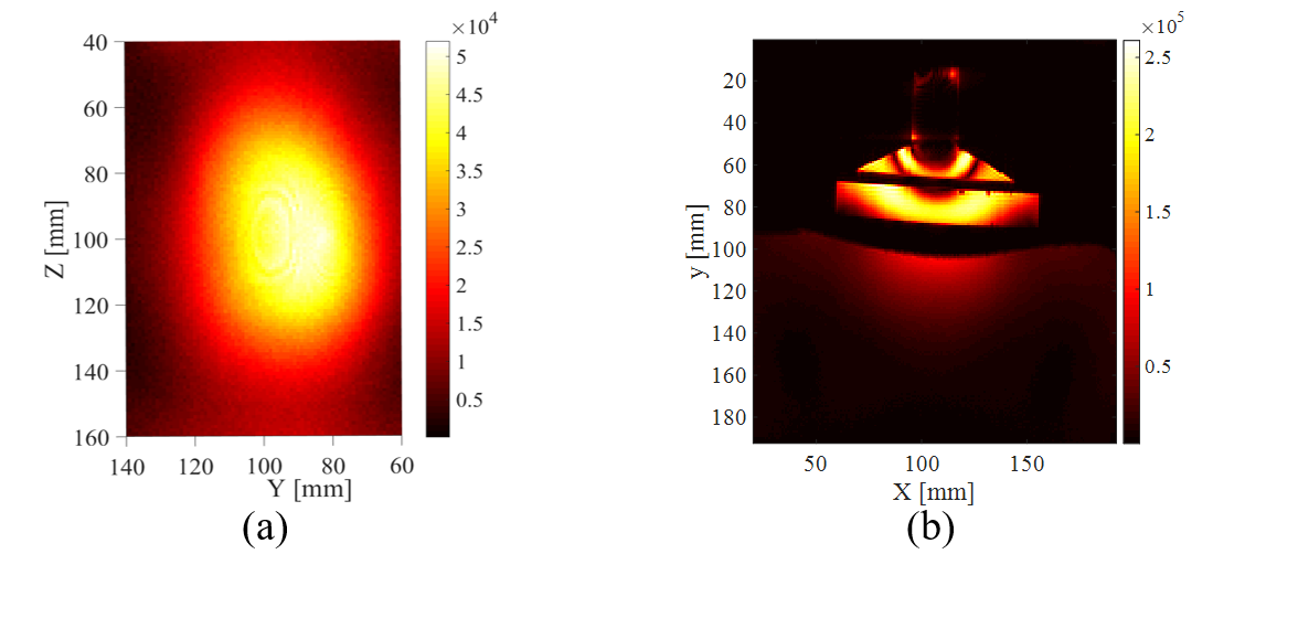
Received signal (a) on a coronal plane 5 cm
below the antenna, (b) sagittal slice.