4414
Monopole Antenna Array for UHF Magnetic Resonance Imaging1Center for Advanced Imaging, University of Quensland, Brisbane, Australia, 2School of Information Technology and Electrical Engineering, University of Queensland, Brisbane, Australia
Synopsis
Birdcage coils have a number of limitations, especially at
INTRODUCTION
Ultra-high field MRI poses a number of challenges for robust radio frequency coil designs. Historically, birdcage coils have shown excellent performance when used as body coils in MRI scanners. They have also been used for imaging of certain body extremities, such as the brain. However, due to limitations associated with an increasing frequency with field strength, birdcage coils have not found application in ultra-high field MRI.1 This difficulty arises because the capacitance of the coil must be reduced as frequency increases, making individual rungs increasingly sensitive to changes in loading, and therefore, changes in impedance. Birdcage coils incorporating variable capacitors in the rungs for individual tuning and matching pose difficulties in construction because the capacitors reduce the amount of conductor in each rung, which adversely affects radio frequency field homogeneity.1,2 Additionally, variable capacitors have relatively large parasitic inductance and create a longer circuit path, resulting in decreased efficiency. As the use of capacitors are the primary drawbacks of birdcage designs, we have opted to investigate the utility of customisable monopole antennas for 3T and 7T MRI brain imaging applications.METHOD
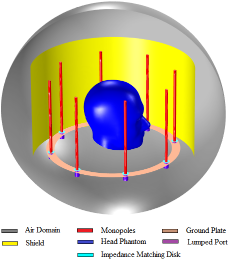
We simulated monopole arrays (example setup shown in Figure 1) with the purpose of optimising model parameters, such as length, diameter and separation between elements.3 For the sake of comparison, we simulated also the birdcage coil design to be able to assess coil performance. 3T and 7T simulations were performed using COMSOL Multiphysics 5.0. A cylindrical saline phantom was used with dielectric constant of 50 and relative conductivity of 4 S/m. Also, simulations were performed in the presence of a human head phantom.4 In our simulations, the head phantom had a relative dielectric constant of 40. We fabricated the monopole array using four monopoles. We also made a loop coil to be able to compare results. For both of the cases the height and radius were kept the same. Copper strips were used to fabricate both the monopole array and the loop coil. The radius of the array was 200 mm and the height of the antenna was 190 mm. The loop coil had the same dimension. The data were collected using HP 8712B network analyser.RESULTS
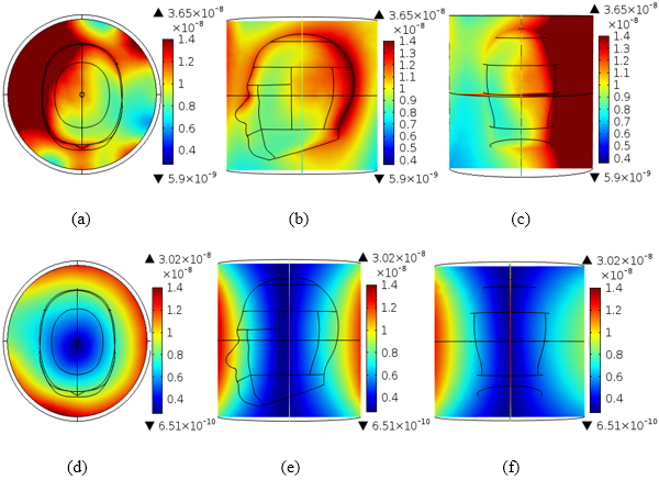
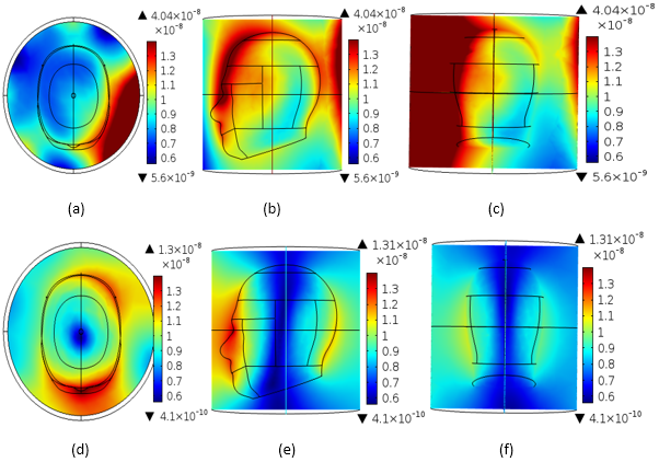
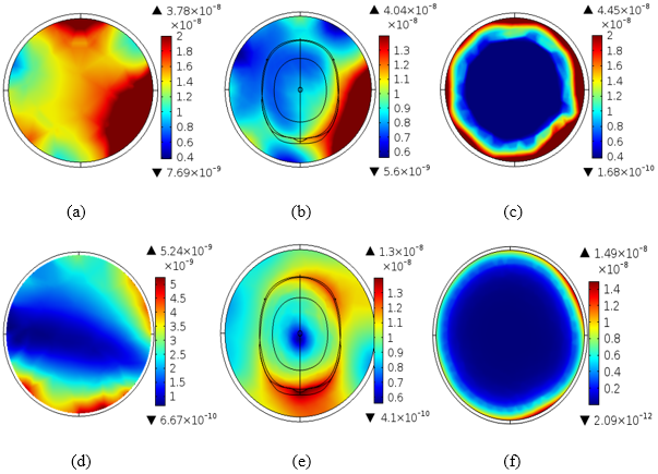
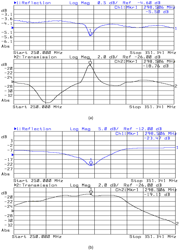
Figure 2(a-c) show the magnetic fields produced by the monopole array and Figure 2(d-e) is the simulation result for the birdcage coil design at 3T (127.74 MHz). Similarly, 7T (298.06 MHz) results are shown in Figure 3. The test simulation results for the monopole array and birdcage coil designs under different loading conditions is provided in Figure 4. We have analysed the field distribution when the coil is unloaded, and loaded using saline and using a head phantom. From Figure 5 we can conclude that we were able to achieve good decoupling between individual monopoles in the monopole array (compare -18.76 dB to -19.11 dB for the loop coil).DISCUSSION
The 3T simulation results show that the monopole array has 20.86% higher field intensity than the birdcage coil. We found that the field homogeneity for the monopole array is also better than for the birdcage coil. In the axial view the monopole array was able to obtain coverage across the entire head whilst achieving sufficient field homogeneity, whereas the birdcage coil was not able to produce the same quality of field. This was also evident in the sagittal and coronal views. In the case of the 7T simulation results, the field intensity obtained using the monopole array was almost 210% higher than for the birdcage coil. In the axial view, the birdcage coil was able to achieve better homogeneity. In the sagittal and coronal views the monopole array did not show any field deficiencies. In the unloaded case, the field intensity for the monopole array was 7.2 times larger than for the birdcage coil, and 3.0 and 3.2 times larger for the saline and human head phantoms, respectively. Notably, in our phantom study the monopole array was able to achieve a better field distribution than the birdcage coil.CONCLUSION
We have compared the utility of 3T and 7T monopole arrays for the purpose of brain imaging. We have shown that monopole arrays can potentially outperform the classical birdcage coil design. Our bench testing confirms that monopole arrays can be decoupled for MRI applications.Acknowledgements
The authors would like to thank the Australian Research Council for linkage project funding (LP130100703).References
1. Dardzinski BJ, Li S, Collins CM, Williams GD, Smith MB. A birdcage coil tuned by RF shielding for application at 9.4 T. J Magn Reson 1998; 131: 32-38.
2. Jianming J, Gary S, Thomas P. On the field inhomogeneity of a birdcage coil. Magn Reson Med 1994; 32: 418-422
3. Stutzman WL, Thiele GA. Antenna theory and design. New York: Wiley; 1981. 202p
4. https://www.comsol.eu/model/absorbed-radiation-sar-in-the-human-brain-2190.
Figures