4413
Microstrip Resonator for High Field MRI with Capacitor-Segmented Strip and Ground Plane1Technical Univ. of Denmark, Kgs. Lyngby, Denmark, 2Danish Research Centre for Magnetic Resonance, Centre for Functional and Diagnostic Imaging and Research, Copenhagen University Hospital, Hvidovre, Denmark
Synopsis
High field MRI coils are often based on transmission line resonators. Due to relatively short wavelength of RF fields, such coils produce uneven field patterns. Here we show, that it is possible to manipulate magnetic field patterns of microstrip resonators in both planes (sagittal and transverse) segmenting stripe and ground plane of the resonator with series capacitors. The design equations for capacitors providing symmetric current distribution are derived. The performance of two types of segmented resonators are investigated experimentally. To authors’ knowledge, a microstrip resonator, where both, strip and ground plane are capacitor-segmented, is shown here for the first time.
Purpose
To increase sagittal and transverse uniformity of the magnetic field in transmission line resonators. An efficient circuit model allowing to design segmented resonators with symmetric current distribution is developed. The described approach to control magnetic field would be useful in the design of coils with uniform field patterns.Background
For the purpose of boosting the efficiency of transmission line coils they are usually operated as resonators. This results in a large standing wave ratio (SWR) on the line. To minimize that, coils based on transmission line resonators are typically shorter than half a wavelength and proper capacitive loading is used to achieve symmetric current distribution along the line1. The resulting current magnitude reduces at the ends of the line due to destructive interference of the incident and reflected electromagnetic waves, as it is shown in Fig. 1 (red dotted curve). It is, however, preferable to have a uniform current distribution. That would result in a more uniform magnetic field in the sagittal plane. Uniform current distribution could be achieved by either segmenting the microstrip with series capacitors2, or using zeroth order resonance3. The advantage of both approaches is that they allow to build resonators of arbitrary length3,4. A uniform current distribution along the resonator, however, does not guarantee the uniformity of the field in the transverse plane. The field distribution in the transverse plane, on the other hand, can be manipulated by segmenting the ground plane of the microstrip resonator5.Methods
The considerations above suggest that in order to improve field uniformity in both sagittal and transverse planes, both conductors, strip and ground plane, of the microstrip line have to be segmented. A circuit model of such a structure is shown in Fig. 2. (b). Series capacitors Cs are inserted in both current-carrying conductors unlike the case shown in Fig. 2. (a)2, where only the stripe is segmented. These capacitors can compensate for self-inductance of the transmission line by introducing opposite phase shift. Imposing a symmetry condition for current distribution we will achieve identical currents in both cases (Fig. 2) if the series capacitors are chosen in the following way:
$$ C_{s}=\frac{sin(\frac{\beta l}{N})}{2 \pi f_{0}Z_{0}(1-cos(\frac{\beta l}{N}))} ,$$
where l is the total length of the segmented transmission line resonator; N is the number of segments after inserting series capacitors (in this example, using two series capacitors will result in N = 3); β is the phase constant; Z0 is the characteristic impedance of the implemented transmission line; f0 = 298 MHz is the operating frequency. Both resonators in Fig. 2 will have identical current distribution corresponding to the blue solid curve in Fig. 1. The curves in Fig. 1 suggest, that the sagittal field distribution for segmented resonator will be more uniform in comparison to conventional resonator. However, the transverse field distribution depends on the implemented transmission line technology and can be estimated by either full wave simulations or measurements.
Results
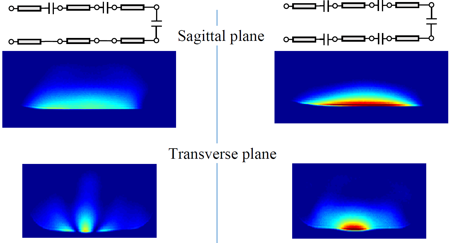
Photographs of the fabricated transmission line resonators using suspended microstrip technology is shown in Fig.3. In resonator with capacitor-segmented strip (refer to Fig. 3 (a)), series capacitors are formed by overlapping adjacent transmission line sections2. The resonator with capacitor-segmented ground plane in Fig. 3 (b) uses lumped components for convenient and identical segmentation of stripe and ground plane. To minimize current discontinuities, each segmentation employs two parallel capacitors having half the required value. In order to evaluate behavior of the designed coil in the presence of lossy tissue, phantom studies were conducted using a 7T system. The measurement results using a saline phantom are shown in Fig.4.Discussion and Conclusion
As can be seen from comparison in Fig. 4, the design with segmented ground plane provides more uniform field in the transverse plane. On the other hand, sagittal field pattern is not as uniform as for the design with uniform ground plane. This shows that the magnetic field patterns of the transmission line resonators can be manipulated in sagittal and transverse planes by segmenting both current-carrying conductors with series capacitors. While the field pattern in the sagittal plane depends on current distribution along the resonator, transverse field pattern depends on implemented transmission line technology and can not be estimated using a simple circuit model. Evenly distributed capacitors were considered in this work (equal value capacitors inserted between equal length line sections). It is expected, that higher homogeneity over a wider field of view could be achieved using unevenly distributed capacitors with variable values.Acknowledgements
The authors would like to thank Danish National Research Foundation (grant DNRF124) and Danish Council for Independent Research (grant 6111-00349A) for partial support of the activities.References
1. Vaughan J. T. et al. High Frequency Volume Coils for Clinical NMR Imaging and Spectroscopy. Magn. Reson. in Med., 1994, Vol. 32, Issue 2, pp. 206-218.
2. Zhurbenko V. Optimal Value of Series Capacitors for Uniform Field Distribution in Transmission Line MRI Coils. Journal of Sensors, vol. 2016, Article ID 3480965. pp.1-7.
3. Panda V. et al. Zeroth-Order Resonator with Stepped Impedance for 7T Magnetic Resonance RF Coil. Proceedings of 24th ISMRM meeting, 3563.
4. Zhurbenko V. et al. Large Field-of-View Transmission Line Resonator for High Field MRI. Proceedings of EuMW2016, pp.1-4.
5. Yan X., Gore J. C., and Grissom W. A. Tuning Microstrip Coil Field Patterns Using Capacitor-Segmented Ground Planes. Proceedings of 24th ISMRM meeting, 3533.
Figures
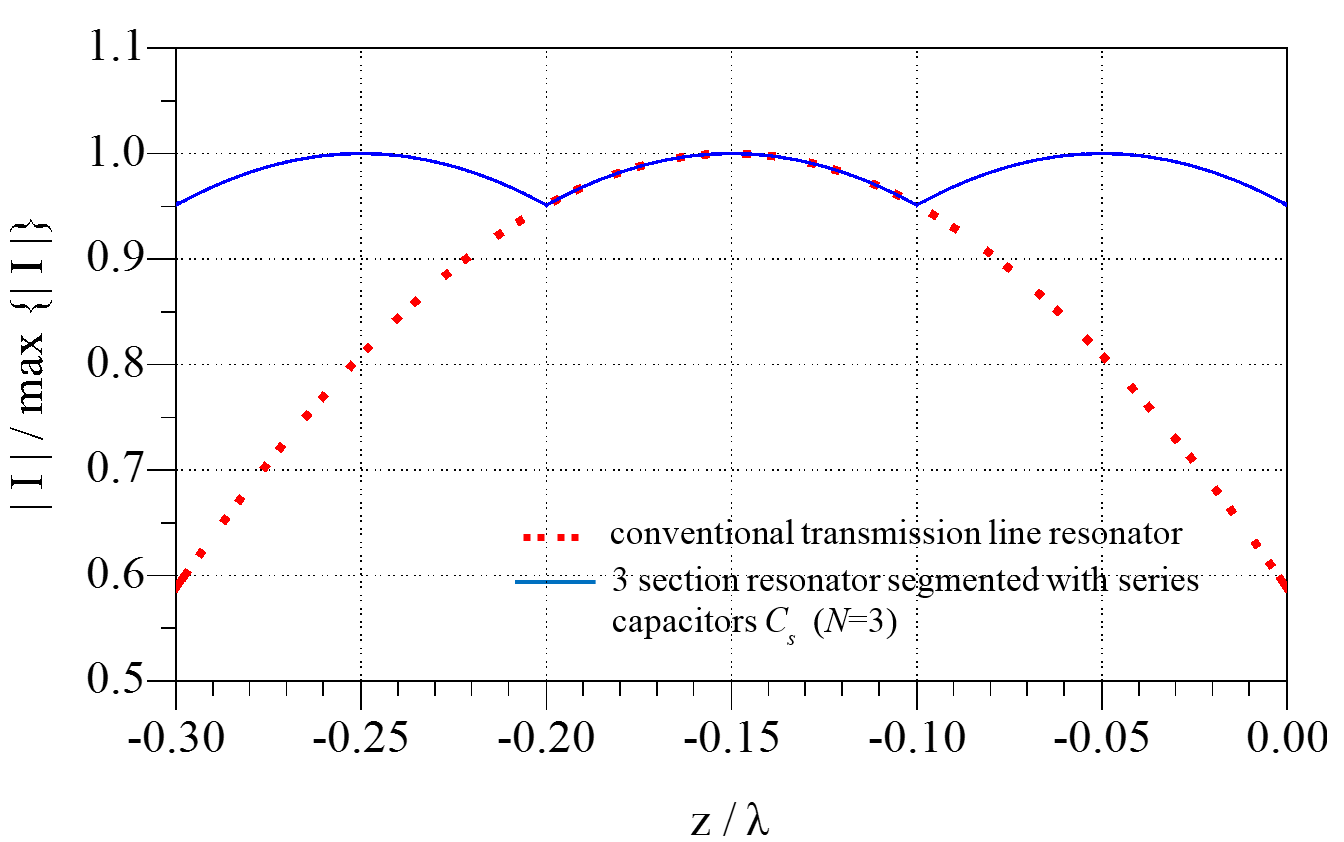
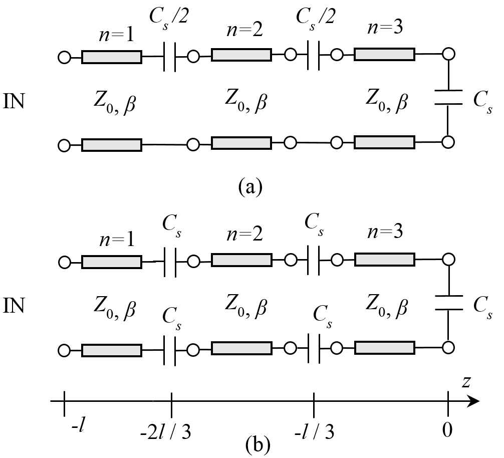
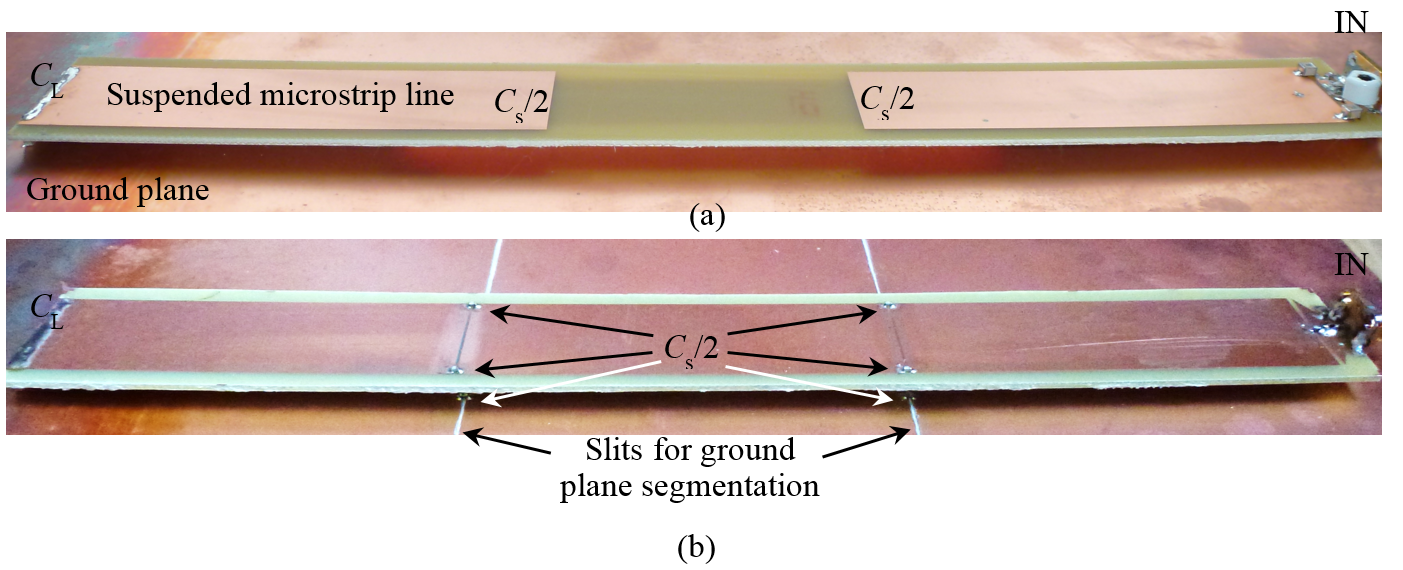
Fig.3. Photographs of the fabricated microstrip resonators
(a) – only stripe is segmented, corresponds to case in Fig.2. (a).
(b) – both, stripe and ground plane are segmented, corresponds to case in Fig.2. (b).