4406
Newly Designed Miniaturized Patch Antenna with High Dielectric Material Plugs1Bio Engineering, Pennsylvania State University, University Park, PA, United States, 2Electrical and Computer Engineering, Michigan Tech University, Houghton, MI, United States, 3Mechanical and Nuclear Engineering, Pennsylvania State University, University Park, PA, United States, 4Engineering Science and Mechanics, Pennsylvania State University, University Park, PA, United States, 5Huck Institutes of the Life Sciences, Pennsylvania State University, University Park, PA, United States
Synopsis
High performance Radio Frequency resonators (RF resonators) produce strong and homogeneous magnetic fields. Due to their large sizes, patch antennas have hardly been considered to be used as RF resonators in Magnetic Resonance Imaging (MRI), especially at high fields. In this work, a newly developed miniaturized patch antenna with high dielectric material plugs was designed, simulated, built and tested at 14.1 T. The simulated and experimental magnetic fields were compared to confirm the performance of the fabricated patch antenna as a RF resonator for MRI.
Introduction
High Dielectric Materials (HDM) have been of great interest in Magnetic Resonance Imaging (MRI) in the past decade. Either a HDM patch was positioned in between the sample and the Radio Frequency resonator (RF resonator) to locally increase Signal to Noise Ratio (SNR) [1], or a HDM resonator was designed as a replacement for conductive RF resonators [2], or HDM plugs were used to design a patch antenna as a quadrature transmit RF resonator at 7 T magnet [3]. In this work, the feasibility of a newly designed miniaturized patch antenna with HDM plugs to be used as a transmit/receive RF resonator at 14.1 T was explored.Method
I. Design and simulation
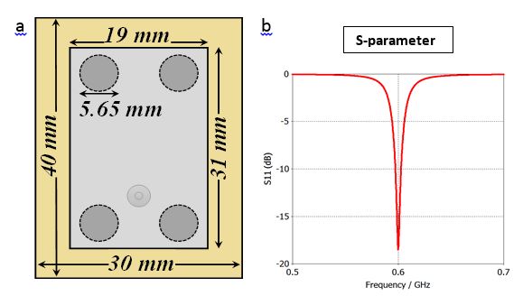
All work was conducted at 14.1 T. Hence, the designed micro-strip patch antenna needed to resonate at f = 600 MHz. The longer dimension (L) of the rectangular metallic patch is related to the half-wavelength (λ/2) at the antenna resonance, which is 250 mm in free space at 600 MHz.
$$ L=λ/2=c0/(2f sqrt(εreff)) $$
where c0 is the speed of light in free space and εreff is the effective relative permittivity of the substrate. The antenna needed to be miniaturized in order to fit in the gradient set (inner diameter: 55 mm).To shrink the size of the antenna, a non-uniform substrate was designed composed of FR-4 (εr=4.8) with four high-permittivity cylindrical pellets (εr = 300 and tanδ=0.004) inserted. The size of the antenna substrate with ground plane was 30 mm × 40 mm and the size of the metallic patch was 19 mm ×31 mm (Fig. 1a). The structure was modeled using CST Microwave Studio (CST of America Incorporated, Framingham, MA, USA). The simulated S11 spectrum, presented in Fig. 1b, showed that the antenna was operating at 600 MHz. The antenna was fed by a 50-ohm coaxial cable and the feeding point was chosen to provide the best impedance matching.
II. Fabrication
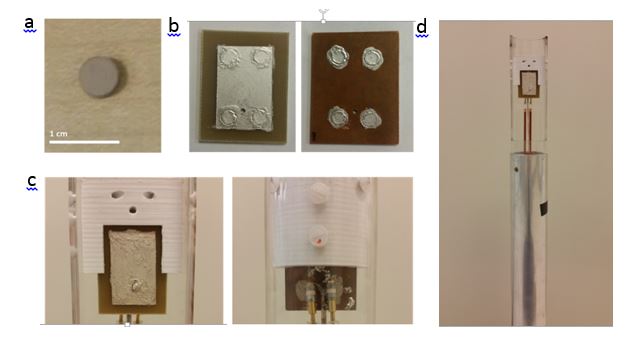
The antenna was fabricated using the dimensions introduced in the simulation. SrTiO3 high permittivity pellets (figure 2a) were home built. The capacitance, the diameter, and the thickness were measured using eight samples of the pellets. The calculated average relative permittivity was 326.71 ± 5.25. One sided printed circuit board (PCB) was cut the same size as the ground plane. Holes were drilled for the pellets and the semi-rigid cable. The pellets were inserted and silver paint was applied to paint a patch (19 mm ×31 mm) that served as the metallic patch antenna conductor. Furthermore, silver paint was also added on the pellets at the ground plane (figure 2b). The antenna was fixed in a premade probe and two variable capacitors were added to be able to fine tune and match the resonance frequency to 600 MHz and 50 ohm respectively. In the case of not being able to tune and match the patch antenna at the Larmor Frequency, the size of the metallic patch was controlled by either adding or removing silver paint.
III. MR Imaging
MR imaging was conducted and a flip angle map of the patch antenna was created using a 1% Magnevist solution in a 15 mL Falcon tube. To get the maximum signal, the minimum echo time (TE) was used. Two images were taken. First, a gradient echo image with a global flip angle of 30 degree was taken followed by a second gradient echo image with twice as much transmission power. The flip angle map was calculated using the double angle method formula [4].
Result and Discussion
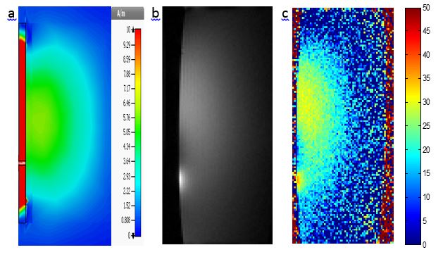
Figure 3 shows the magnetic field of the RF resonator (B1) of the middle of the patch antenna in the simulation (Figure 3a), the gradient echo image of water phantom with flip angle of 30 degree (Figure 3b), and the flip angle map of the patch antenna (Figure 3c). The simulated B1 and the flip angle map, which is directly proportional to B1, show very similar behavior. The simulated and calculated B1 results diverge near the feeding point. This discrepancy is due to the solder that bulges out at the feeding point. The current that flows around the bulge at the feeding point adds an extra magnetic field in this area. Nevertheless, there are some drawbacks of patch antennas as RF resonators in MRI, such as concentrated fields around a feeding point. Although it has some limitations, patch antennas may serve as an alternative to standard RF coils in MRI.Acknowledgements
This work is supported by the National Science Foundation under Award DBI-1353664References
[1] Q. X. Yang, J. Wang, J. Wang, C. M. Collins, C. Wang, and M. B. Smith, “Reducing SAR and enhancing cerebral signal-to-noise ratio with high permittivity padding at 3 T,” Magn. Reson. Med., vol. 65, no. 2, pp. 358–362, 2011.
[2] K. Haines, T. Neuberger, M. Lanagan, E. Semouchkina, and A. G. Webb, “High Q calcium titanate cylindrical dielectric resonators for magnetic resonance microimaging,” J. Magn. Reson., vol. 200, no. 2, pp. 349–353, 2009.
[3] S. Oh, E. Semouchkina, T. Neuberger, M. T. Lanagan, B. Zhang, C. M. Deniz, Collins, and C. M, “Miniaturized Patch Antenna for Traveling-wave Excitation?: Pilot Study at 7 T MRI,” in proceedings international society magnetic resonance medicine, 2013, vol. 21, no. c, p. 0389.
[4] C. H. Cunningham, J. M. Pauly, and K. S. Nayak, “Saturated double-angle method for rapid B1+ mapping,” Magn. Reson. Med., vol. 55, no. 6, pp. 1326–1333, 2006.
Figures