4350
Design and Construction of Shielded Enclosures for MRI1Imanova Ltd, London, United Kingdom
Synopsis
A significant limiting factor for electronic devices within the scanner room is the electromagnetic interference (EMI) that they generate. Also, electromagnetic radiation from the scanner can interfere with the safe operation of electronics in close proximity to the scanner. We describe the development of an approach that enables researchers to fabricate inexpensive and reliable shielded enclosures without access to extensive engineering facilities. Our investigation explores the relative advantages and disadvantages in the design and construction of three different shielded enclosures and concludes with a performance evaluation by measuring the frequency dependent attenuation of electromagnetic signal intensity.
Introduction:
A wide variety of MRI experiments benefit from the use of a peripheral electronic devices within the scanner room. A significant limiting factor for many devices is the electromagnetic interference (EMI) that they generate, which can cause image artifacts. Furthermore, electromagnetic radiation from the scanner can interfere with the safe operation of electronics in close proximity to the scanner. To address these issues we have developed a reliable and cost-effective approach to designing and fabricating shielded enclosures. Here we report on the performance of three different shielded enclosures that we have developed, and summarise the relative advantages and disadvantages in their design and construction.Materials and Methods:
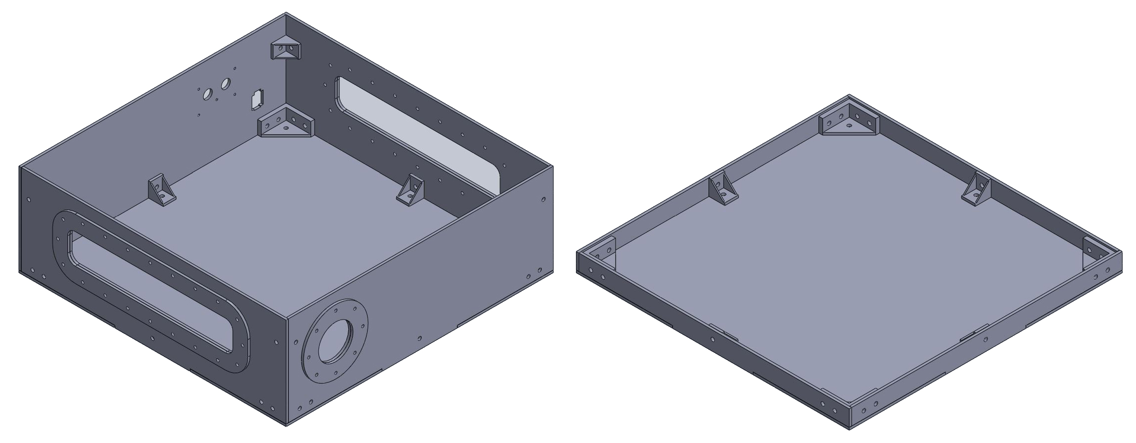
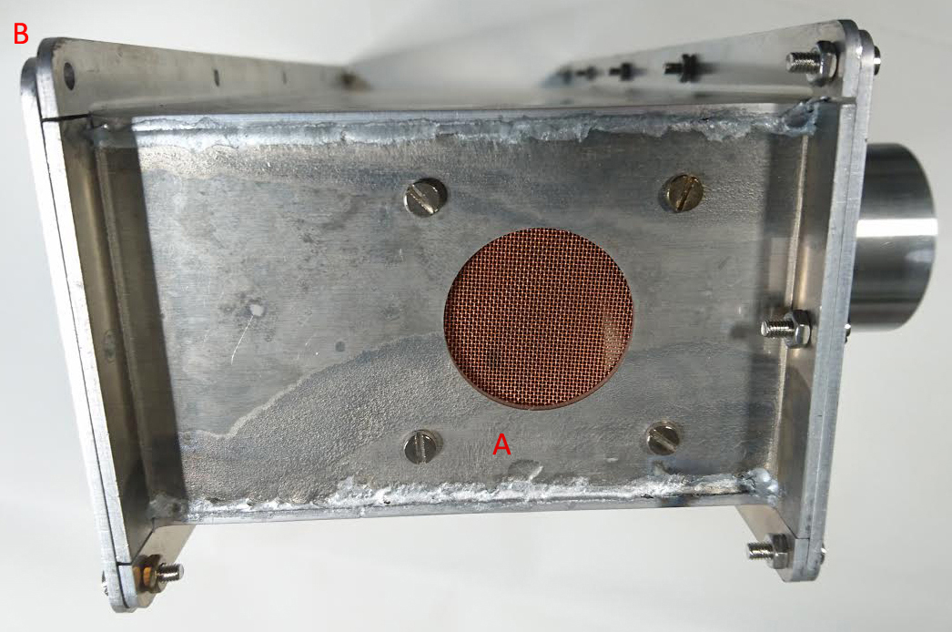
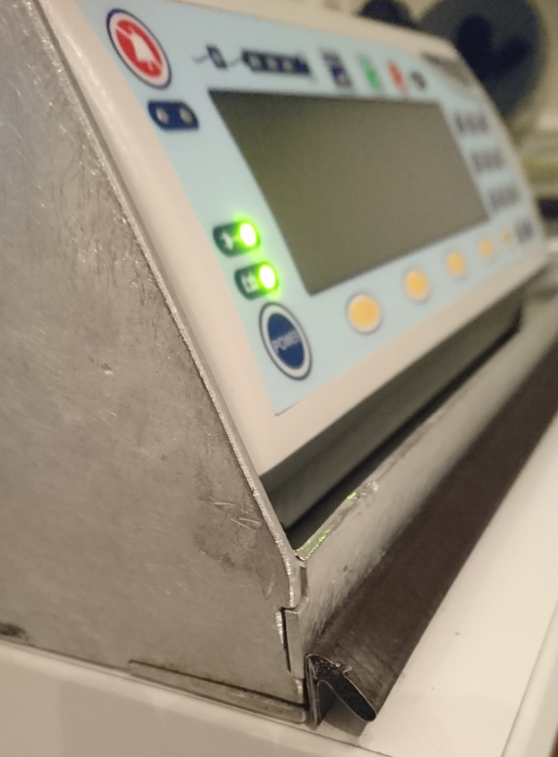
One of the simplest and most effective ways to create a Faraday cage is to build a five-sided metal box with a lid that completes the shielded enclosure. Our enclosure components were designed (Figure 1) as collection of interlocking plates, using an evaluation copy of Autodesk Fusion360. This design was exported as a .dxf file and laser cut from 2mm aluminium sheet. Aluminium sheet provides a structurally rigid and inexpensive non-magnetic material that can be accurately cut. The individual plates were cleaned and deburred, and the mounting holes were centre-drilled to create countersunk regions for screwheads. Aluminium corner braces (sparkfun PRT-10228) were used to connect and support the wall components, providing a built-in gasket compression stop for the lid assembly. The components were secured using M3 brass machine screws, enabling a simple, accurate and demountable way to assemble the enclosure. This approach is preferable to welding, as the heat required to weld two metal plates can create severe distortions, and if not carefully controlled, can result in irreversible damage to the enclosure. It is also preferable to avoid sheet metal bending (Figure 2), as this is difficult to implement accurately without a CNC controlled bending press. An adhesive elastomer gasket (Figure 3) was applied to the perimeter of the lid, providing a flexible and conductive seal. This type of conductive fabric gasket has significant advantages over beryllium copper finger stock, which needs to be cleaned periodically and can be easily damaged if over-compressed. Finally the joints and screwheads of the enclosure were shielded with adhesive copper tape to create an unbroken conductive surface. Our most recent and complex enclosure is a shielded box for a portable projector. An aperture was incorporated into the enclosure to accommodate a power line filter and an additional aperture was included to hold a shielded RJ45 socket. Further openings were included for the image output and cooling fan. These openings were covered with micro-fine copper mesh.Results:
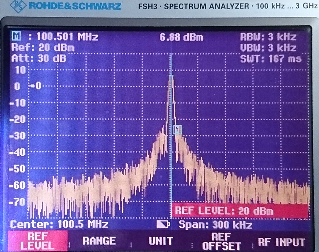
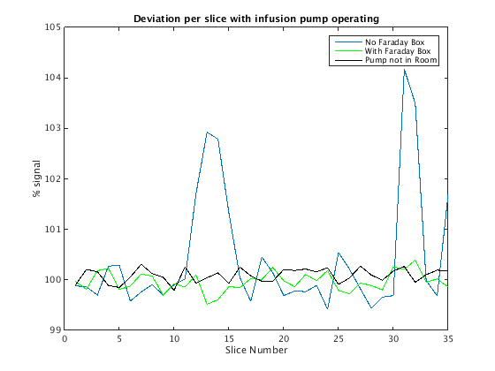
Initial radio frequency (RF) analysis was performed using a Rohde & Schwarz FSH3 spectrum analyser, together with a Rohde & Schwarz SML03 signal generator. By placing a small transmission antenna inside the enclosure, we were able to determine that the shielding provides between 100dB and 120dB attenuation to RF signals up to 3GHz (Figure 4). Further evaluation of our enclosures was performed on a clinical Siemens 3T Tim Trio (Siemens Healthcare, Erlangen, Germany) by using a selection of fast spin-echo (FSE) sequences to generate large amplitude RF pulses at high speeds. This was performed with the shielded enclosure mounted to a secure shelf at a distance of one meter from the scanner bed (5mT field strength). Despite the enclosure being ungrounded relative to the scanner room cage, the level of RF attenuation was such that no measurable interference was detected by the scanner (Figure 5.)
Discussion:
Due to stringent safety and electromagnetic interference requirements, electronic devices for MRI can be prohibitively expensive, or in some cases, no MRI-safe equivalent device exists. Additionally, particularly in fMRI, there is an increasing use of electronic devices in close proximity to the scanner, creating a requirement for enclosures that are effectively shielded. Our approach demonstrates a reliable and inexpensive procedure that does not require access to sophisticated engineering facilities. Future work will focus on refining this approach by investigating the electromagnetic behaviour of such enclosures. This will be achieved by using electromagnetic field simulator software based on finite element methods, with particular emphasis on radiated emission from apertures and the control of internal reflections and standing waves.Acknowledgements
The Design of Shielded Enclosures - cost effective methods to prevent EMI. Louis T. GneccoReferences
No reference found.Figures