4348
Cost-effective RF Signal Transmit-Receive chain at 9.5mTSamarth Singh1, Darshan Shivaramu Keelara1, Chennagiri Rajarao Padma1, Rashmi Rao1, Imam Ahmed Shaik1, and Sairam Geethanath1
1Medical Imaging Research Centre, Dayanand Sagar Institutions, Bangalore, India
Synopsis
A cost-effective RF Signal Transmit-Receive chain with independent transmit and receive coil was designed with inexpensive off-the-shelf electronic components, costing around 175 US dollars. A Direct Digital Synthesizer (DDS) module was controlled using an Arduino Uno R3 microcontroller board. RF pulses were timed to precision using Arduino IDE, and the 405 kHz sine wave required to operate a 9.5 mT system was pulsed to a transmit coil. This signal was detected successfully by a custom-made surface coil. While the transmit, pulse was at 1.12Vpp from the DDS module, the surface coil successfully picked up a 1.75 Vpp signal.
Introduction
Ultra-Low Field(ULF) MR could play an important role in neurocritical applications, owing to its portability1, and ability to provide clinically relevant images of the brain2, complementing traditional MRI systems. Previous research3 also shows a portable earth field NMR spectrometer at an operating cost of under 200 $. The emerging research interest in ULF MRI motivated for construction of a cost-effective RF signal transmit-receive chain with a target field operating at 9.5 mT. Inexpensive and readily available electronic components were utilized, resulting in a total cost of around 175 US dollars (refer Table 1).Methods
The RF Signal Chain had an independent transmit and receive coil, which were custom designed. The Arduino UNO R3 microcontroller board, based on the ATmega328P (8-bit AVR RISC-based microcontroller), formed the pulse programmer. This board was chosen due to its ease of programming, robustness and a low cost of 25 $. It was utilized to digitally program the DDS module, operating based on the AD9850, which is an integrated device that uses Direct Digital Synthesis (DDS) technology coupled with an internal D/A converter and comparator to form a complete, digitally programmable frequency synthesizer and clock generator function. It is capable of producing pure sine waves up to 40 MHz with minimal noise. The device also provides five bits of digitally controlled phase modulation, which enables phase shifting of its output in increments of 180°, 90°, 45°, 22.5°, 11.25°, and any combination thereof. The DDS module acted as the RF Pulse transmitter, pulsing 405 kHz of pure sine waves for stimulating a coil to operate at 9.5 mT. An Arduino controlled reed relay switch, COTO 8L02-05-00, was utilized to implement accurate pulsing of the sine wave. Arduino provides its own IDE for development, which offers an abstraction to embedded C programming utilized for controlling the ATmega328P. A simple pulse sequence was designed using the Arduino IDE, allowing sub micro-seconds precision timing, and is shown in Fig 2. For testing purpose, a total TR of 12 seconds was utilized, with Ton equal to Toff. The pulse duration was kept at 5 seconds, with a starting delay of 5 ms. This test was to ensure the receiver coil would get sufficient time to pick up the transmitted pulse, contrary to conventional systems where the two are required to be decoupled. Open source libraries4 to operate the DDS module were utilized. These libraries were incorporated into the pulsing program for interfacing the Arduino UNO R3 with the DDS module. The 405 kHz pulsed sine wave was fed to the transmit coil, which was a solenoid of diameter 11cm wound around a PVC pipe, through an RF amplifier operating with 12V DC and 1 A current. 2 baluns were incorporated to avoid reflection of the pulsed sine wave into the reed relay switch. The receive chain consisted of a single surface coil which fed its output directly to a Tektronix TBS1102B-EDU oscilloscope.Results
The RF Signal Transmit-Receive chain was successfully operated with an RF pulse of 405 kHz. The field in the transmit coil upon pulsing RF was measured by a Lutron EMF-828 EMF tester, and the Z component was measured to be 0.26 µT. Intermediate results at each stage are collated in Fig 3. As seen in Fig 3a, the DDS module output is at 405 kHz, and a pure sine wave can be observed. Fig 3b depicts the relay output, which is the RF pulse as compared to the signal generator output. Figure 3c shows an amplified output of the RF amplifier, with a constant delay of 0.2µs added due to the introduction of 2 balun circuits utilizing LC components. Figure 3d shows an output frequency of 405 kHz being detected by the receiver coil, when compared to the relay output.Conclusion
The RF Signal Transmit-Receive chain successfully pulsed and detected a 405kHz sine wave through an independent coil setup, and with a total build cost of under 175$. It can be employed as part of a low field brain MRI system, operating at 9.5 mT. Future work includes digitizing the signal from the receiver coil utilizing the inbuilt ADC on the Arduino UNO, which is capable of sampling frequencies around 40kHz. LT1568 based filtration for isolating received signal from noise shall be used. The received signal’s centre frequency shall be shifted to 0 Hz from 405 kHz by mixing the received signal with the 405 kHz sine wave to obtain an intermediate frequency, which ensures the ADC’s sampling criterion is met.Acknowledgements
No acknowledgement found.References
1. Cooley, C. Z., Stockmann, J. P., Armstrong, B. D., Sarracanie, M., Lev, M. H., Rosen, M. S. and Wald, L. L. (2015), Two-dimensional imaging in a lightweight portable MRI scanner without gradient coils. Magn. Reson. Med., 73: 872–883. doi:10.1002/mrm.25147 2. Sarracanie, Mathieu, Cristen D. LaPierre, Najat Salameh, David E. J. Waddington, Thomas Witzel, and Matthew S. Rosen. 2015. “Low-Cost High-Performance MRI.” Scientific Reports 5 (1): 15177. doi:10.1038/srep15177. http://dx.doi.org/10.1038/srep15177. 3. Carl A Michal, A low cost spectrometer for NMR measurements in the Earth’s magnetic field. Measurement Science and Technology,2010 4. m0xpd’s Shack Nasties. DDS and DueDDS Libraries. March 9, 2014. http://m0xpd.blogspot.in/2014/03/dds-and-duedds-libraries.htmlFigures
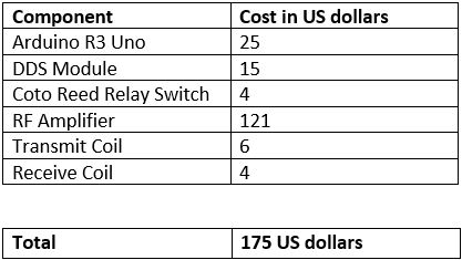
Table 1 showing costs of major individual components in the RF Signal Transmit-Receive
chain. Total cost incurred is approximately 175 dollars, excluding
interconnects and power supply.
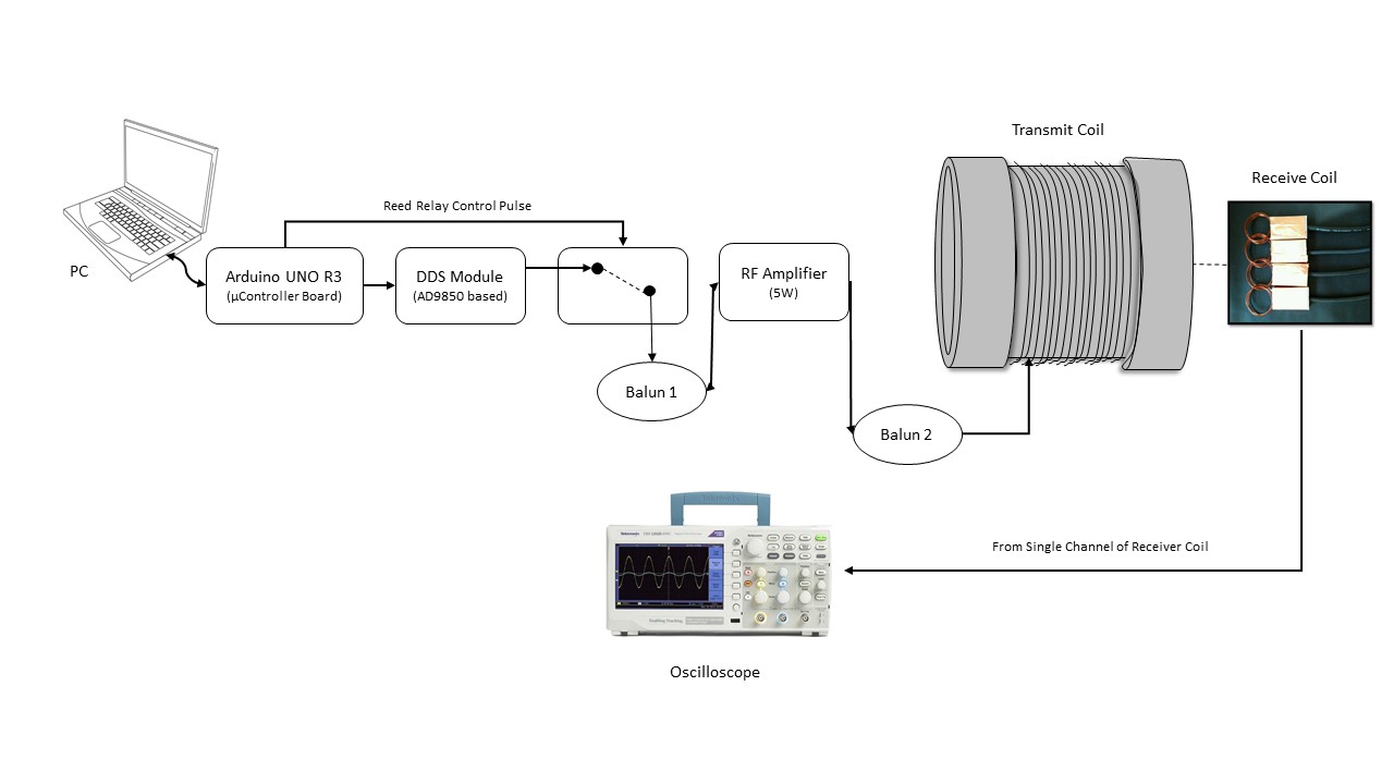
Figure
1: A schematic of the setup for the RF Signal Transmit-Receive Chain. A single
channel of the 4-channel receiver coil was utilized to detect the transmitted
pulse of 405 kHz and the output was displayed on the oscilloscope
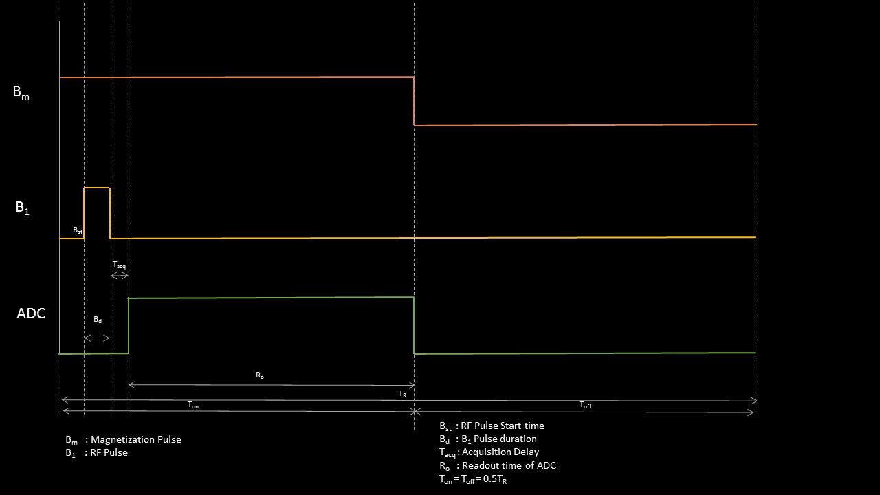
Figure
2: Pulse sequence diagram for the pulse programming implemented using the
Arduino IDE. The ADC readout is a part of the future work, to ensure the
digitized signal sample can be used on the system for further processing.
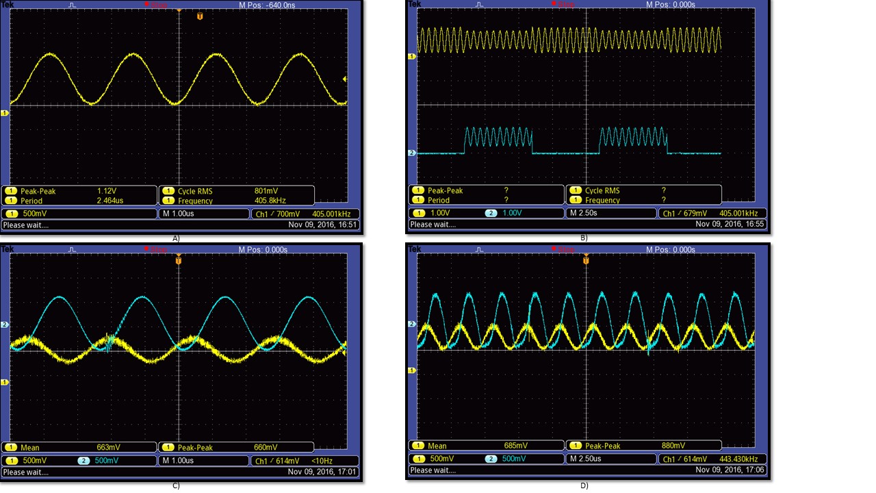
Figure
3 Output collection from intermediate stages of the MR Signal Transmit-Receive
chain. A) DDS module output B) Blue Channel: Output of Relay, Yellow Channel:
Output of the DDS module. Arduino switches the relay on for 5 seconds
C) The yellow channel is the reed relay output, which is 660 mV peak-peak, and
post amplification, the output voltage becomes ~1.75 V peak-peak. D) The yellow channel represents the transmitted
pulse to the transmit coil, at ~685mV peak-peak, and the blue channel
represents the received signal from one channel of the 4-channel wrist coil, at
1.75V peak-peak.