4347
Prototype Hardware of FPGA Controlled Multi-Channel All-Digital RF Transmitter for Parallel Magnetic Resonance Imaging1Aselsan Inc., Ankara, Turkey, 2Electrical-Electronics Engineering Department, Ihsan Dogramaci Bilkent University, Ankara, Turkey, 3National Magnetic Resonance Center, Ihsan Dogramaci Bilkent University, Ankara, Turkey
Synopsis
In this study, prototype hardware of FPGA Controlled Multi-Channel All-Digital Transmitter for Parallel Magnetic Resonance Imaging is presented. The transmitter system consists of a RF power amplifier and a digital signal generator to feed each channels and a user interface computer to control the signal type, amplitude, phase, and frequency of targeted pulse. Digital signal generator uses a novel method which is IQ Pre-Modulation Delta Sigma Modulation Based Digital Single Side Band modulator and enables frequency, phase, and amplitude modulation schemes. The prototype hardware is produced to feed a 12-channel RF-coil, thus RFPA module consists of 12-PA are implemented.
Purpose
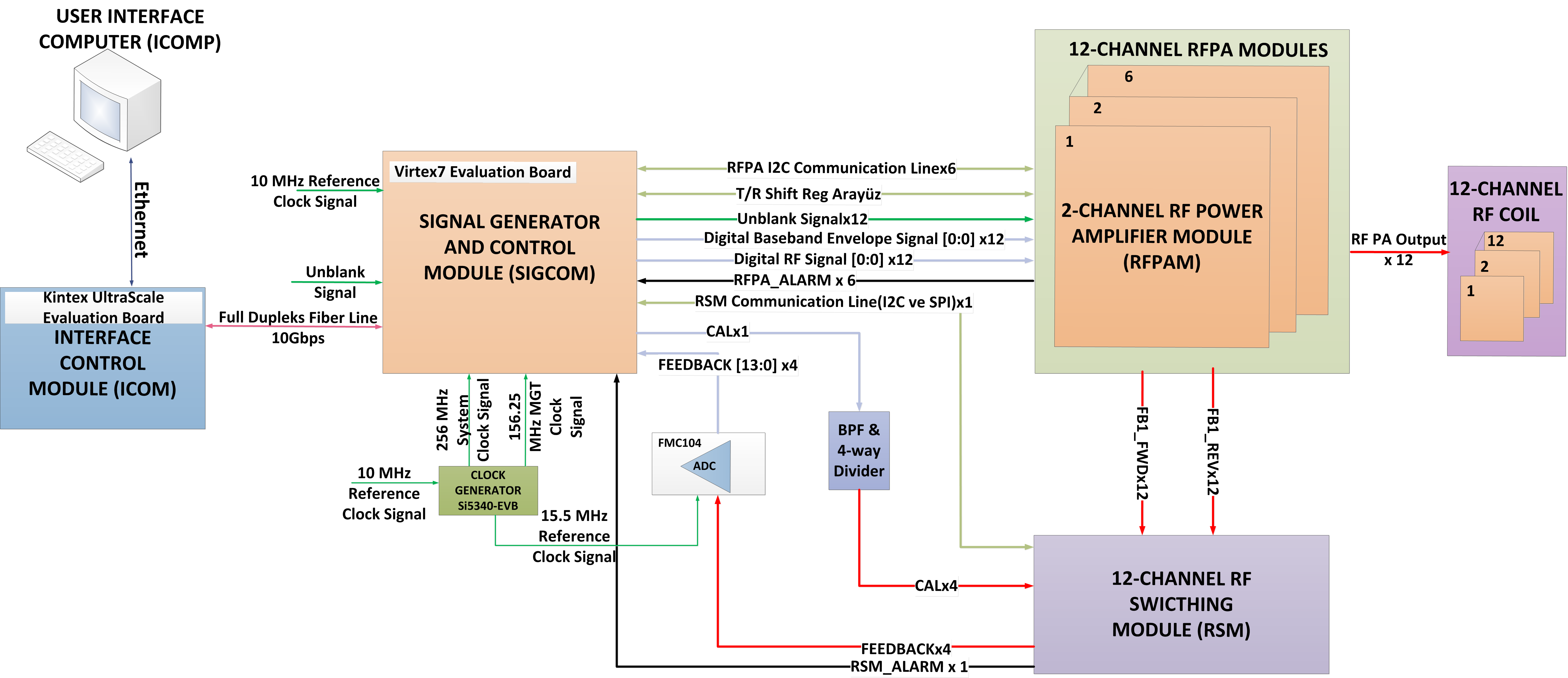
In conventional MRI single output high power analog amplifiers are used for feeding the transmit coils [1]. However, studies are progressing to make multi-channel transmitters with low power RF amplifiers, dedicated to each channel. With this new hardware for MRI, better image quality and lower SAR is expected to be realized. In this study, prototype hardware of FPGA controlled multi-channel all-digital transmitter for parallel magnetic resonance imaging is presented. The transmitter system (Fig. 1) consists of a RF power amplifier and a digital signal generator to feed each channels and a user interface computer to control the signal type, amplitude, phase, and frequency of targeted pulse. Digital signal generator uses a novel method which is IQ pre-modulation delta sigma modulation (DSM) based digital single side band (DSSB) modulator and enables frequency, phase, and amplitude modulation schemes. The prototype hardware is produced to feed a 12-channel RF coil, thus RFPA module consists of 12-PA are implemented.Methods and Results
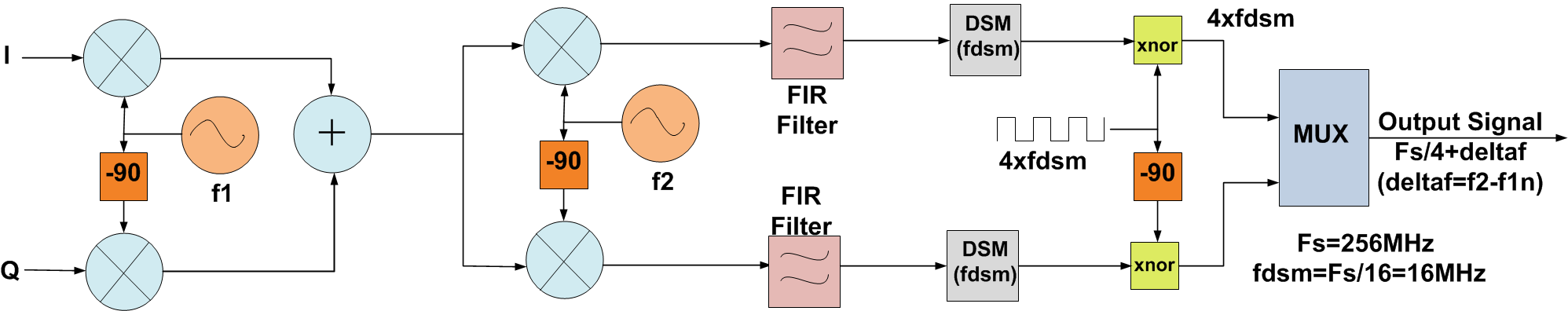
One of the critical components in the multi-channel all-digital MRI transmitter is the digital signal generator (DSG). DSG consists of two FPGA boards which are communicated via fiber optic line. The user can control signal type, amplitude, phase, frequency of each RF channel separately by user interface computer (ICOMP). These data will be transferred to the interface control module (ICOM) via Ethernet communication. ICOMP and ICOM are located outside of the MRI scanner room. Signal generator and control module (SIGCOM), which has the, IQ pre-modulation DSM based DSSB modulator [2] shown in Fig 2, gets the sequence information from ICOM by fiber optical line and generates the digital signal. Delta sigma analog to digital converters are used to digitize the envelope signal such that the amplitude information is hidden into the pulse width of the DSM output pulses [3].
In the SIGCOM implementation, I and Q components of input signal are modulated and summed at IF (f1) frequency. In proposed system, f2 is kept constant and f1 is changed according to the desired frequency of the output such that f2-f1=deltaf where deltaf is the desired offset to the MRI center frequency. Summed signal is fed into the DSM based DSSB modulation. In this configuration, fclock in the DSSB modulator is taken at fdsm and the sampling frequency then becomes 4×fdsm. At the output of the first two multiplexers in I and Q channels, the carrier frequency becomes fdsm±deltaf with SSB modulation. Then, I and Q channels are further multiplexed at 4×fdsm with the sampling frequency of 16×fdsm. The carrier frequency at the circuit output results in 4×fdsm±deltaf.
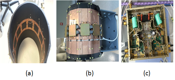
6 on-coil RFPA modules consisting 2 RFPA each are produced to feed 12-channel transmit coil array (Fig.3). According to power level entered by the user, digital attenuators arrange each RFPA output power. In order to satisfy safety requirement, forward and reverse power of each RFPA is monitored and VSWR is calculated. As seen in Fig.1, with 12-Channel RF switching module (RSM) and FMC104 ADC, feedback signal is obtained from each channel to calibrate power and correct the signal.
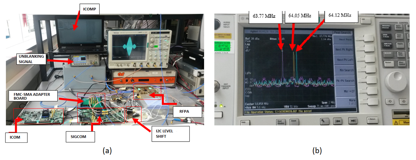
The proposed all-digital transmitter prototype hardware is built and tested with the setup constructed in the lab as seen in Fig.4(a) . With 2 FPGA boards, 12-channel all digital modulator is implemented successfully and the output of each digital modulator is fed into RFPA which has maximum 600W peak power with adjustable power output range of 30dB. Also, Fig.3(b) shows frequency spectrum of three different RF channel output with different carrier frequency and it is seen that the lower sideband signal is suppressed by 50dB in the experiments.
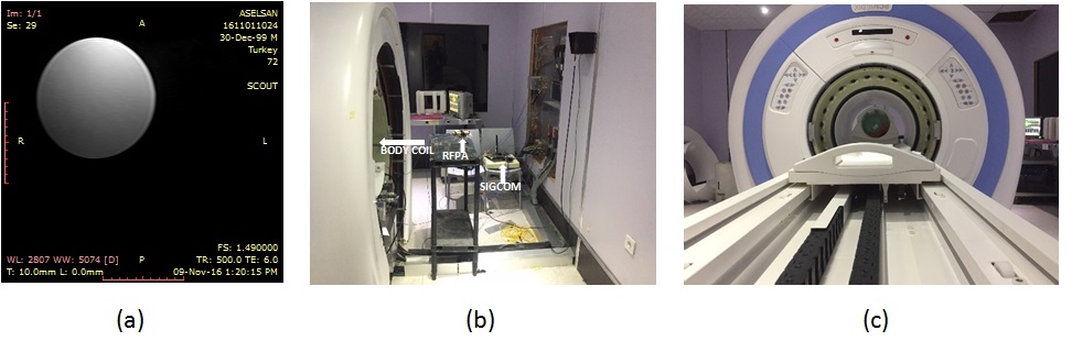
In Fig.5(a) axial MR image of a cylindrical water phantom is shown. In order to show the functionality of the prototype hardware one of the RFPA modules is connected to the body birdcage coil of the SCIMEDIX scanner and used for quadrature excitation as shown in Fig.5(b-c).
Conclusion
In summary, FPGA controlled multi-channel all-digital transmitter architecture is proposed. 12-channel TX coil system with on coil RFPAs and DSG is implemented. As each TX channel has its dedicated DSG and RFPA amplitude, phase, frequency and pulse envelope can be controlled individually. Also FPGA boards gives the ability to easy integration to the conventional MRI scanners, however, the integration of the prototype to a 1.5T scanner is proceeding.Acknowledgements
This work is funded by Technical and Scientific Research Council of Turkey (TUBITAK)References
[1] N. Gudino, J.A. Heilman, M. J. Riffe, O. Heid, M. Vester and M. A. Griswold, “On-coil multiple channel transmit system based on class-D amplification and pre-amplification with current amplitude feedback”, Magnetic Resonance in Medicine, Volume 70, Issue 1, pages 276–289, July 2013
[2] Weaver, D.K., “A third method of generation and detection of single sideband signals”, Proc. IRE, Dec. 1956, pp. 1703-1705.
[3] M. Nielsen and T.. Larsen, “A Transmitter Architecture Based on Delta-Sigma Modulation and Switch-Mode Power Amplification,” IEEE Transactions On Circuits And Systems—Ii: Express Briefs, vol. 54, no. 8, August 2007
Figures