4346
Real time gain stabilization for PET detectors in PET/MR1GE Healthcare, Waukesha, WI, United States, 2GE Healthcare, Palo Alto, CA, United States
Synopsis
Accurate quantitation in PET requires good stability of the detector gain. The challenging thermal environment of the detector in a PET/MR system (proximity to gradients, induced eddy currents, heat from RF shield, ...) makes accurate temperature compensation important. Current solutions rely on characterization of detector response together with real time temperature measurement for a predictive (open loop) gain control. This work presents a method of gain control that operates in real time by analyzing spectral information of singles events, permitting closed loop gain control in the presence of temperature gradients or count rate variations.
Background
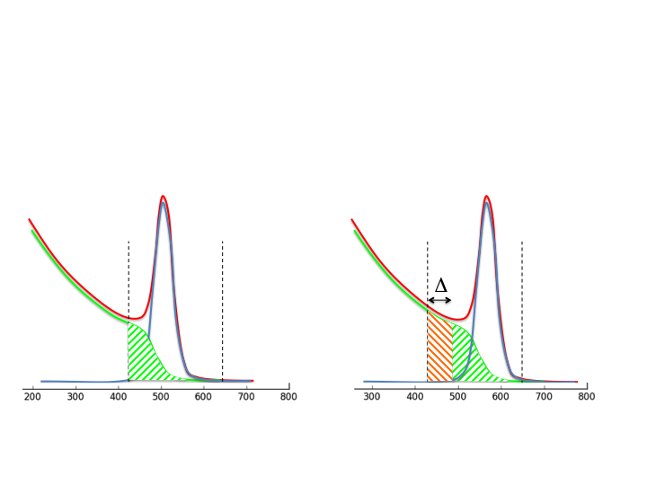
Accurate gain control of a PET detector ensures that only events of the correct energy are used for image reconstruction. Energy windowing is necessary for scatter rejection. Even so, a fraction of events in the window will have undergone scatter (Figure 1a), and this reduces image contrast and degrades quantitative accuracy. Scatter correction estimates the shape and size of the scatter distribution, and attempts to correct for this bias. Scatter correction is sensitive to peak stability: if gain of the detector increases, more scatter will be admitted into the acceptance window (Figure 1b). This is why peak shift results in a change of the reconstructed activity: while the number of detected events goes up with a positive peak shift (more scatter accepted), the resulting correction means the calculated activity goes down (over-correction). On the GE SIGNATM PET/MR, temperature compensation is currently done by characterizing the detector thermal response, and changing the bias voltage of the silicon photomultipliers based on the measured temperature [1, 2]. During thermal transients, this can result in small residual gain errors of a few %. The present work addresses these.Methods
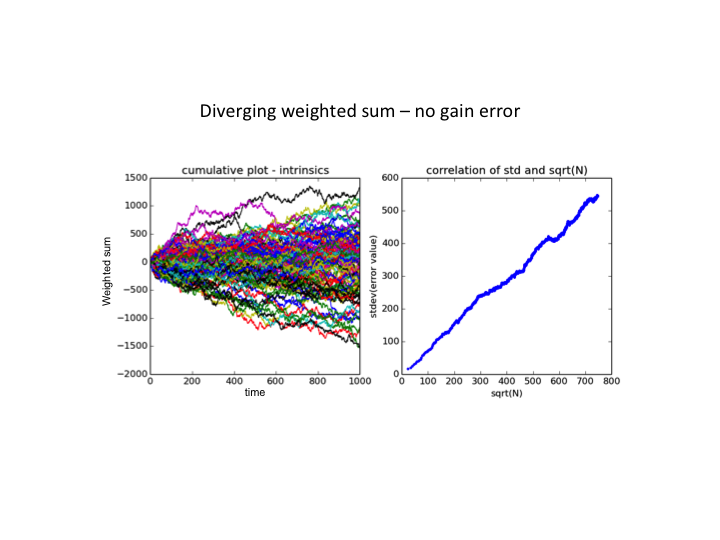
Singles events from PET detectors (including both position and energy information) were obtained while a spiral gradient operated to induce strong thermal gradients in the system. The coefficients of the normal thermal control mechanism were set away from the optimal control point so thermal change resulted in peak shift, which allowed us to more clearly observe the impact of the new control algorithm on gain stability. For a given area of detector (either 12 or 36 crystals), events were binned into 9 separate energy windows, and a weighted sum of counts in these windows was computed. Windows and weights were chosen such that this weighted sum would average to zero when the detector gain was correctly set. Due to the random nature of radioactive decay, the sum will slowly diverge from zero (random walk) even when gain is correct (Figure 2). A criterion was developed that only applied a gain correction if the weighted sum exceeded a specific threshold, namely $$ M = \sum w_i c_i\\ N = \sum c_i\\$$ and change gain only when $$M^2 > \alpha (N + N_0)$$ where $$$\alpha$$$ is a statistical factor that ensures only statistically significant changes result in a gain adjustment, and $$$N_0$$$ is a damping term that prevents many small gain steps. The algorithm was initially developed in C, and used to process list mode data to demonstrate speed and accuracy of response. After this, it was programmed in VHDL to run in real-time on the detector, where processing a single event could be done in 200 ns, and gain is updated as soon as a statistically significant shift (as small as 0.2%) is detected. Events were then obtained from PET acquisitions with the new control loop running.Results and Discussion
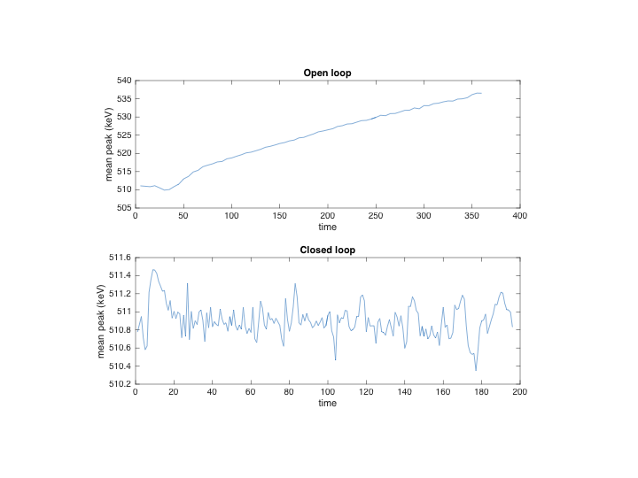
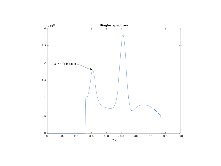
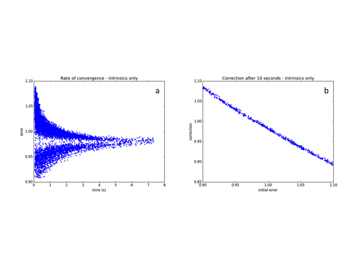
When thermal compensation is not using the optimal coefficients, the temperature change of the detectors results in a shift in gain (Figure 3, top), but applying the compensation algorithm results in stable peak as temperature changes (Figure 3, bottom). Looking more closely at the distribution of peak shifts, we could observe the effect of a thermal gradient in the Z direction, with individual devices in the block array (Figure 4a, 4c) having up to 2% difference in gain. This gradient is too small to be observed with the 2 thermistors per detector unit (48x64 mm2, 12 SiPM arrays), but was visible after per-block gain correction was applied. By applying gain control per-device (16x16 mm2 of detector area) the residual gain errors are reduced to a fraction of a percent (Figure 4b, 4d). Some of the windows used for sampling the spectrum are centered around the well-resolved 307 keV peak (Lu-176 intrinsic radiation, Figure 5), which permits the detector gain to remain stabilized without an external source; randomly initializing the gain of blocks in the range [0.9, 1.1], the algorithm recovered gain to < 1% within 10 seconds (Figure 6). By careful selection of weighting factors, gain stability was made independent of scatter fraction.Conclusion
Feasibility of an algorithm to provide real-time gain control of a PET detector in the MR environment has been demonstrated. The algorithm has been implemented in VHDL and demonstrated to run in real time (200 ns / event) in our PET detector. The very high stability that this produces should permit greater quantitative certainty and may open new avenues for research in PET/MR.Acknowledgements
The authors would like to thank their colleagues at GE Healthcare for helpful discussions, in particular Dave McDaniel and Tim Deller.References
[1] Kim et al., Compensation for thermally-induced loads on PET detectors from MR stimulus in simultaneous PET/MR, ISMRM 2014, p780.
[2] Levin et al., Design Features and Mutual Compatibility Studies of the Time-of-Flight PET Capable GE SIGNA PET/MR System. IEEE TMI. 2016; 35(8):1907-14
Figures