4340
Continuous SWIFT: Analog Leakage Compensation Utilizing an Embedded System1German Cancer Research Center, Heidelberg, Germany
Synopsis
Methods for simultaneous excitation and acquisition enable measurements of signals with ultrashort T2* relaxation times. In this work, a method was developed and implemented to analogously compensate leakage of the excitation pulse into the receiver channel due to imperfections in coil tuning and the quadrature hybrid utilized in cSWIFT setups. The setup was enhanced with an embedded system, a vector modulator and a summing unit to subtract the leakage from the signal. Feasibility of the real-time compensation was demonstrated. Leakage was reduced by up to -40 dB.
Purpose
Methods for simultaneous excitation and acquisition enable measurements of signals with ultrashort T2* relaxation times because of TE = 0. Recently, proof of principal imaging has been shown: cSWIFT1,2, STAR3, CEA4. cSWIFT setups utilize a quadrature hybrid to isolate transmit and receiver channels. Due to imperfections of the hybrid and tuning, parts of the excitation pulses leak into the receiver channel. The aim of the presented work was the development and implementation of a setup to subtract this leakage analogously before post amplification and signal digitalization in order to avoid problems with signal quantification. The correction method was designed to be applied in real-time during the radio-frequency sweep.Methods
All experiments were performed on a whole-body 7T MR system (Magnetom 7T, Siemens Healthcare, Erlangen, Germany).
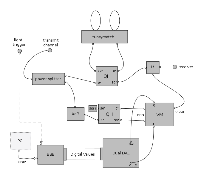
Hardware. Figure 1 shows a schematic including all components of the setup. Crucial components were the vector modulator (VM) ADL5390, the dual digital-to-analog converter (DAC) AD9767 (both by Analog Devices) and an embedded computer system (BeagleBone Black, BeagleBone.org Foundation, Oakland Charter Township, MI, USA). The embedded computer includes two programmable real-time units (PRUs) clocked with 200 MHz. The DAC contains two digital-to-analog converters with a maximum update frequency of 167 MHz. The VM’s input signal was split off the excitation pulse by an in-house build power splitter optimized for 297.155 MHz. The VM can add a phase from -180° to 180° and apply an amplitude gain from -30 dB to 3 dB to its input signal. To superpose the VM’s output signal with the measured signal containing the leakage, a passive, in-house built summing unit was used.
Software. To control the VM in real-time, a software for the PRUs was designed and implemented in assembler code. The tasks of creating the digital output and organizing memory usage were subdivided to the two available PRUs. The calculation of the needed compensation values was implemented using ICE (Image Calculation Environment, Siemens Healthcare, Erlangen, Germany) and was performed on the image reconstruction computer. The compensation values were transmitted to the embedded computer via TCP/IP. Since the leakage does not change strongly between consecutive sweeps, compensation values can be updated less than every sweep, which is required due to the delays in data transmission (<100ms).
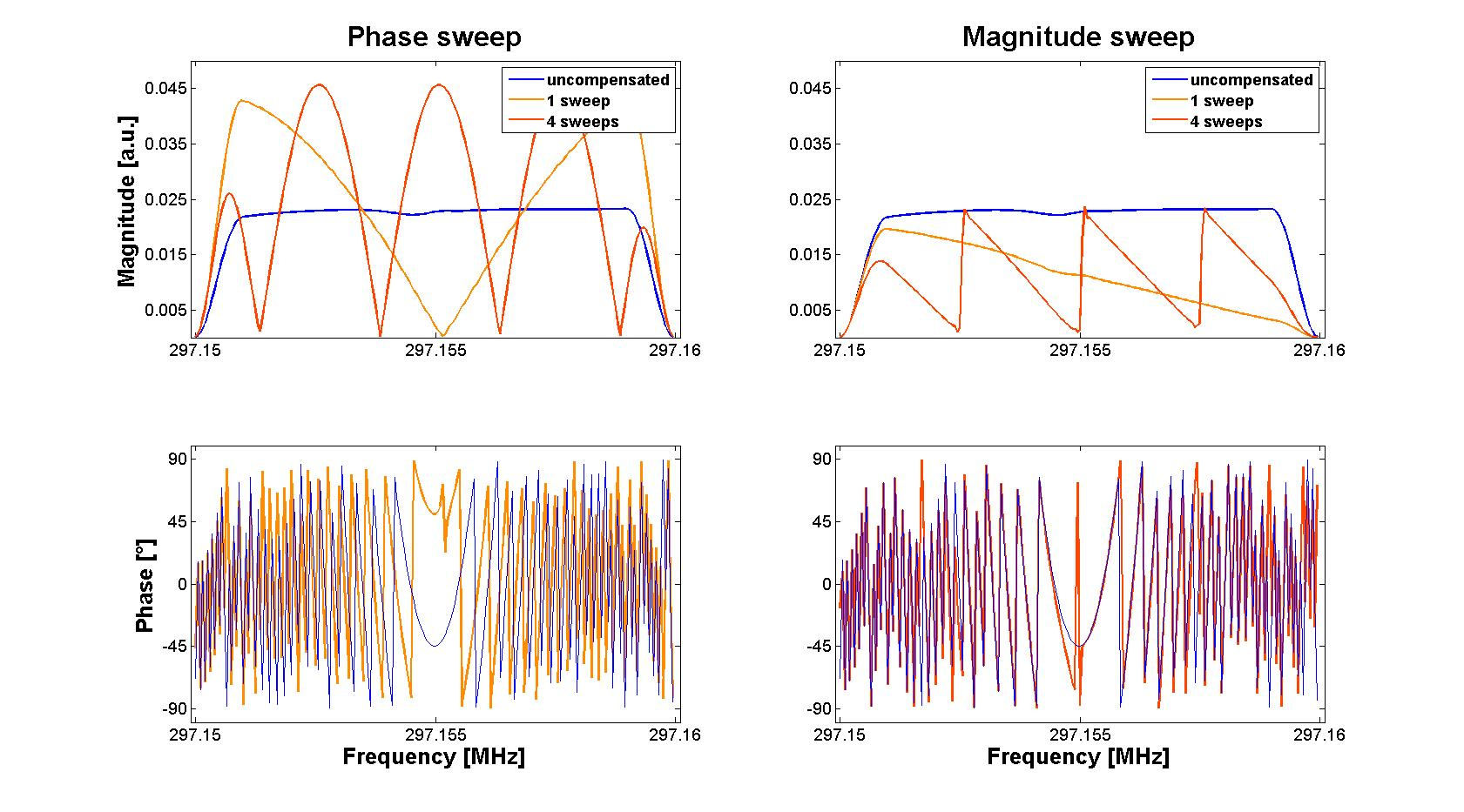
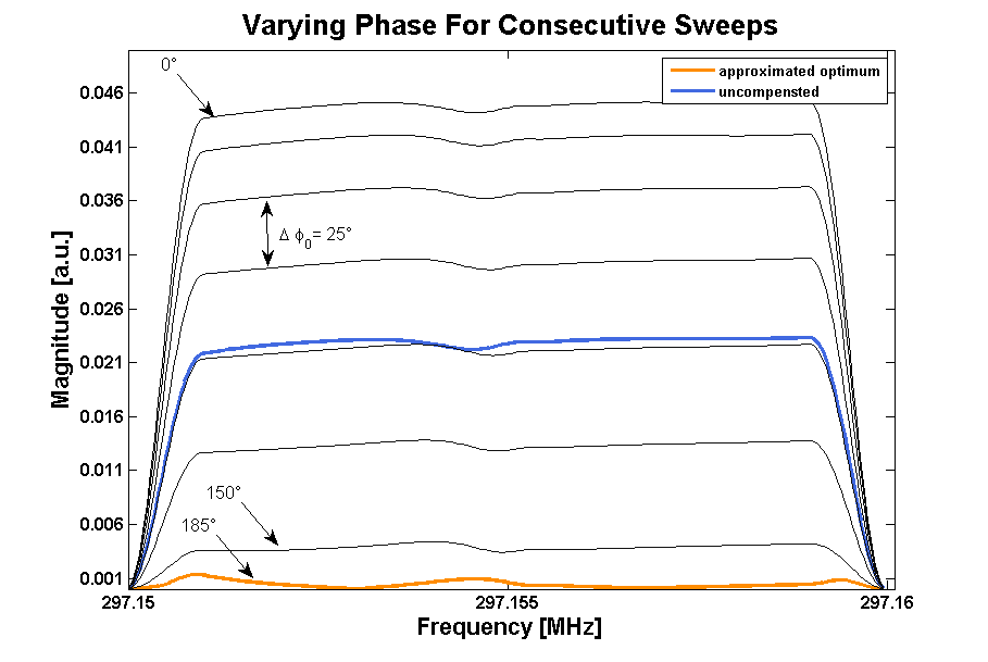
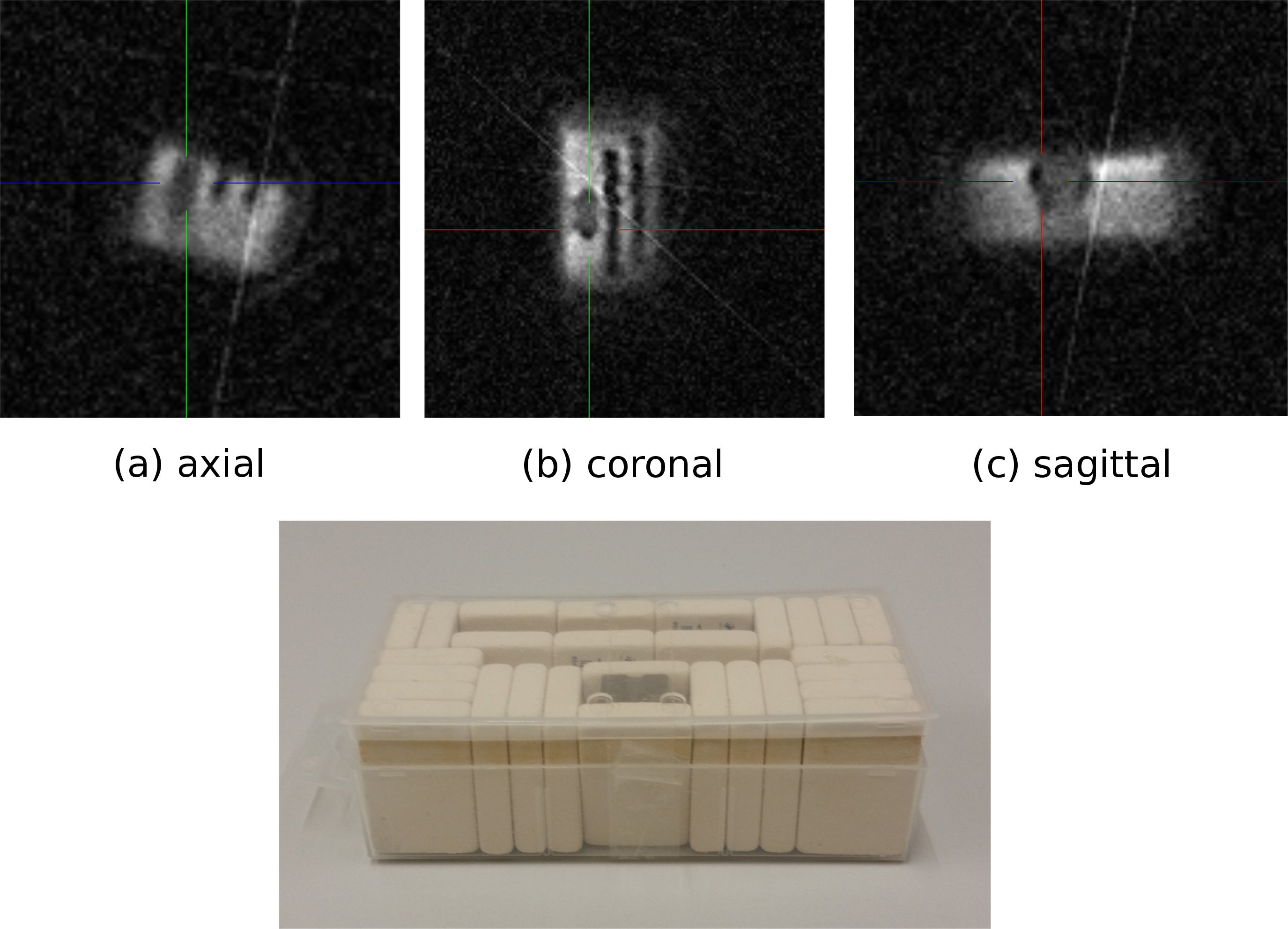
Experiments. Before performing measurements, the attenuator -XdB was adjusted manually, so that the magnitude of the VM's output at maximum gain was somewhat higher than the leakage's magnitude. To demonstrate feasibility, single sweeps with particular patterns at the VM’s output were performed. First, the phase offset was swept over the full range (360°) from one to four times during four frequency sweeps. Therefore, the data showed one to four minima in magnitude. Based on the position of the minima the relative phase offset for leakage compensation was estimated. Secondly, the VM’s control was set to the phase offset with the best compensation and then the amplitude was swept during frequency sweeps (see Fig. 2). Between each sweep a non-compensated reference measurement was performed (not shown). Additionally, measurements in which the phase offset was varied for consecutive sweeps but held constant over the sweep were performed (see Fig. 3). An image of a rubber phantom was acquired using the setup (Fig. 4).
Results
Figure 2 and Fig. 3 show the effect of summing both signals as well as the compensation depending on the VM output phase offset. The saw-tooth pattern in Fig.2 shows that the output of the summing unit decreases with increasing magnitude and the phase offset being set correctly. Figure 3 shows the major decrease of the leakage between -24 dB to -40 dB even with the phase offset being constant over the sweep. Figure 4 shows an image of a rubber phantom, acquired with the setup.Discussion and Conclusion
The presented results show the capability of the setup to compensate unwanted leakage analogously. The phase offset sweep presents a fast method to find a suitable initial phase offset value. Figure 3 shows the necessity to vary the phase offset of the compensation vector during the sweep for optimum suppression of the remaining leakage. The used sinusoidal and saw-tooth patterns show that all components are sufficiently fast to apply dynamic compensation in real-time during the sweep. In the next step, dedicated leakage optimization algorithms will be developed.
In conclusion, the presented approach allows for strong suppression of leakage before post amplification and signal digitalization. Therefore, higher excitation amplitudes are feasible and imperfections in tuning can be mitigated, while signal to noise ratio is greatly enhanced.
Acknowledgements
The authors thank Barbara Dillenberger and Christian Kindtner for their support.References
[1] Idiyatullin D et al., J. Magn. Reson. (2012) 220: 26-31.
[2] Maier F et al., ISMRM conference 2016, e-poster 3555
[3] Sohn, S.-M. et al., Magn. Reson. Med. (in press) doi:10.1002/mrm.26464
[4] Özen AC et al., Magn. Reson. Mater. Phy. (2015) 28(6): 565-576
Figures