4339
Measuring Slice Profiles Across the Industry With the ACR Phantom1Simply Physics, Baltimore, MD, United States
Synopsis
As part of mandated yearly performance evaluations on over 120 GE, Siemens, Philips and Toshiba 1.5T scanners, the ACR phantom was used to make 2555 measurements of RF slice profiles and thicknesses. Aggregated slice profiles are plotted showing clear differences between vendors both in terms of ‘squareness’ and FWHM thickness. With a target slice thickness of 5.0 mm the measured thicknesses ranged from 4.21 to 6.65 mm! The affect that interslice gap has on measured profiles (RF crosstalk) is demonstrated for T1 weighted sequences. A very surprising dependence of measured thickness on slice position on the ACR phantom is demonstrated.
Introduction
Each MRI vendor uses their own set of proprietary RF excitation pulses. When a particular slice thickness is chosen for an imaging sequence is it safe to assume that this is what we get? How ‘square’ is the excitation profile? How close can adjacent slices be without unacceptable overlapping of side lobes resulting in crosstalk? Actual slice thickness affects resolution, SNR and the possibility of crosstalk. This paper examines using the ACR phantom to answer these questions and points out a previously unexpected limitation of this phantom.Methods
The ACR phantom has a structure with two overlapping lines with +/- 10:1 slopes that is used to measure slice thickness. (1) Software was developed to extract the intensity profile through each line and determine the FWHM slice width. The profiles from each line were normalized, overlapped and combined.
1) More than 500 annual performance evaluations were performed on over 120 different 1.5T magnets from four major vendors. During those tests, a total of 2555 RF slice profiles of T1 and T2 weighted scans using SE, GRE and FSE sequences were obtained using each site’s ACR phantom. The normalized profiles from each type of sequence were averaged to yield aggregate RF profiles for each vendor.
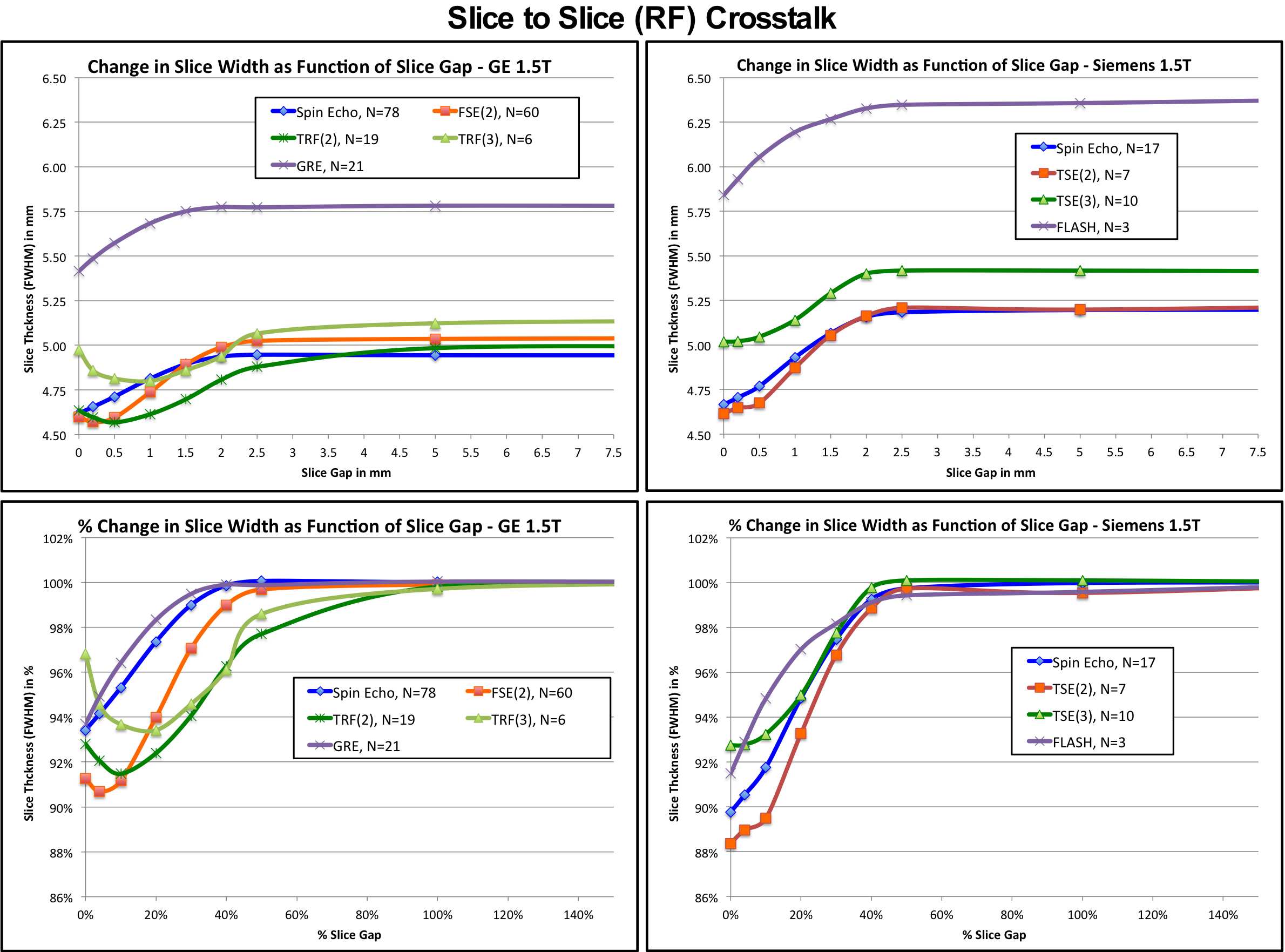
2) Early in the ACR accreditation program, (circa 2004), the ACR required that physicists yearly evaluate RF crosstalk by looking at how the SNR in the flood region changes as slices get closer together. This requirement has been dropped because it was too difficult to obtain reliable, reproducible measurements of SNR that would correlate well with changes in the excited slices. However, with automated software to extract detailed slice profiles, it is possible to examine how the measured slice shape and FWHM thickness change as a function of slice gap. 221 studies were obtained using typical T1-weighted imaging sequences (SE, GRE, FSE with small ETLs) on GE and Siemens 1.5T scanners. Each study consisted of 9 scans centered on the slice thickness block with the slice gap ranging from 10 mm (200% gap) down to 0 mm.
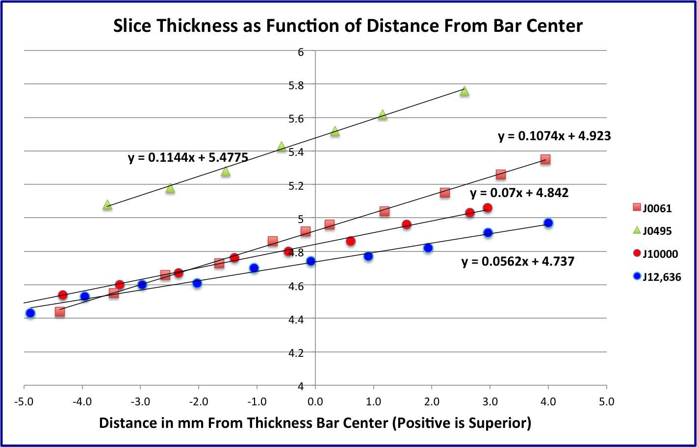
3) It was observed that slices superior to the bar center appeared thicker than those inferior to the center. All of the previously obtained data sets were re-analyzed and the slice thicknesses were plotted as a function of slice position. Linear regression was performed on each aggregate data set.
Four ACR phantoms ranging from less than a year old to more than 12 year years old were scanned at multiple slice positions superior and inferior to the slice thickness block center and the measured thicknesses were plotted as a function of slice position.
Results
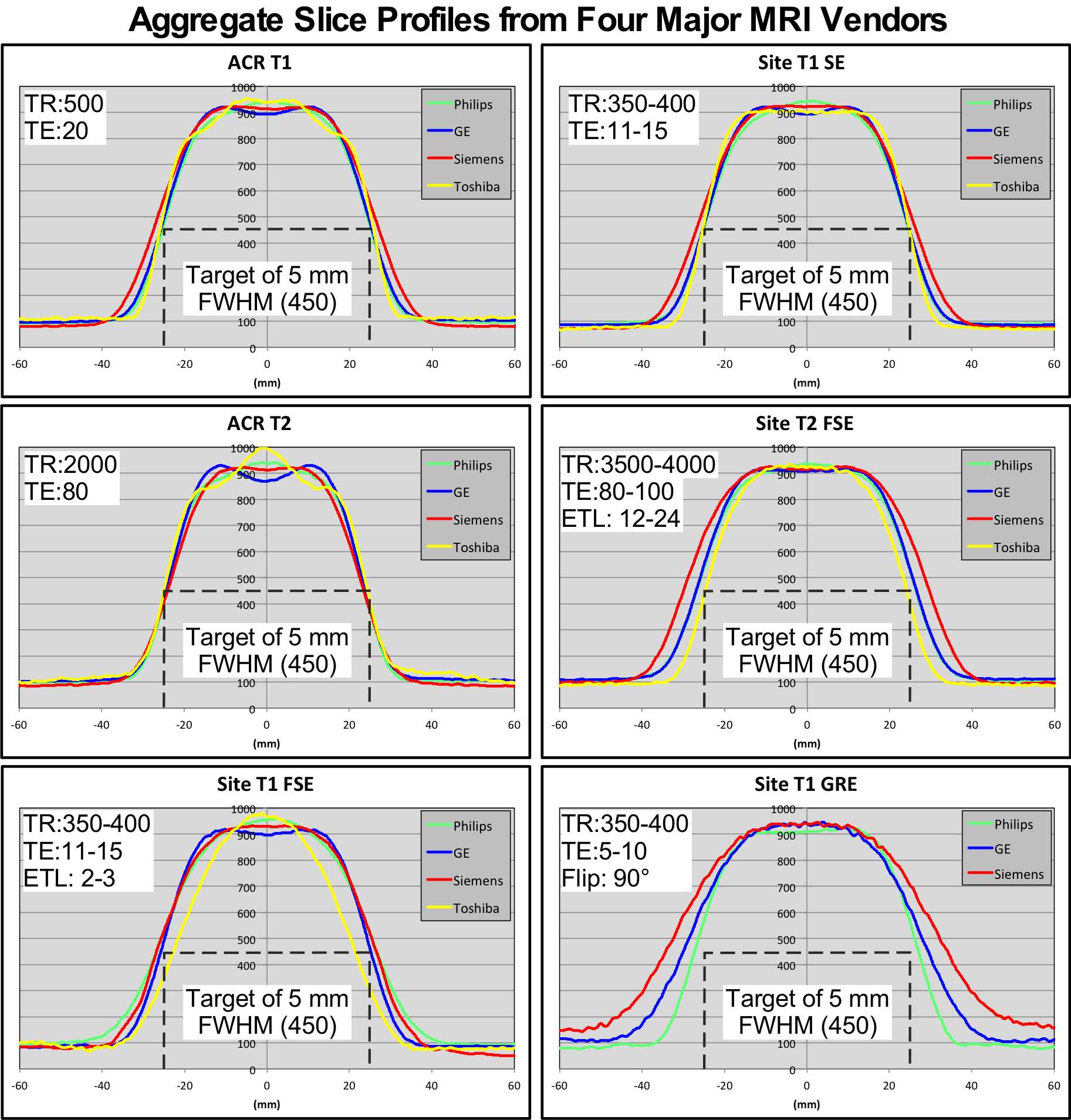
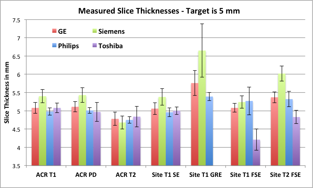
Figure 1 depicts the aggregated slice profiles for six different types of imaging sequences. Figure 2 presents bar graphs of the measured slice thicknesses for these sequences with error bars.
The top two plots of figure 3 show how the measured slice thicknesses vary as a function of slice gap for different T1 weighted sequences on GE and Siemens scanners. To better compare the performance of each sequence, the bottom plots show the same data with the slice thicknesses normalized to the thickness of each sequence at 10mm (200%) gap.
Slice thicknesses as a function of slice position are shown in figure 4. The two oldest phantoms have a slope of a little over 0.1 mm thickness per 1mm change in slice position while the newest phantom’s slope is 0.056 mm per 1mm.
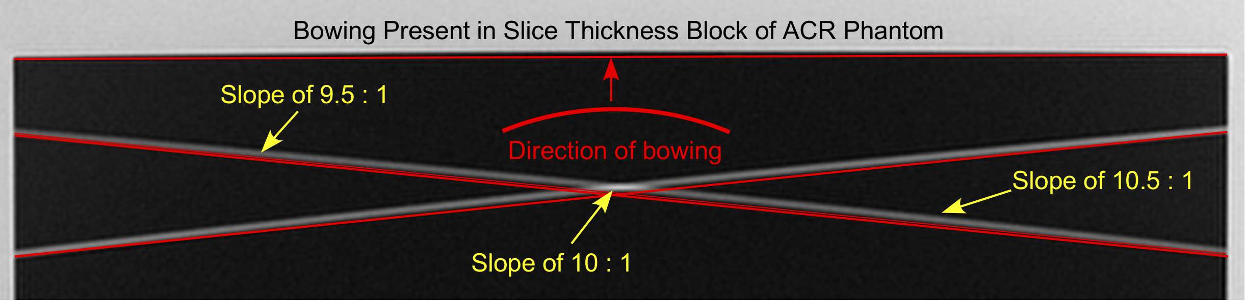
Figure 5 displays a high resolution coronal scan through the slice thickness block. The superimposed lines make the presence of bowing obvious.
Discussion
The ACR spec for slice thickness is 5.0 ± 0.7mm. While there are differences in the details of the profile shapes, most of the sequences fall within this range. The exceptions are Toshiba’s FSE T1 (4.21), GE’s GRE (5.76), Siemens’ GRE (6.65!) and Siemens’ FSE T2 (6.02) In general, GE and Philips fall close to the target value, Toshiba is on target or smaller and Siemens is consistently above, sometimes way above.
RF crosstalk begins at roughly 40% slice gap. Simple sequences (GRE and SE) show less changes while FSE sequences show more complicated changes. The thicker Siemens slices show more crosstalk than the thinner GE slices.
Bowing in the ACR phantom can cause errors in slice thickness measurements depending on slice location. Most ACR submissions are within +/- 2mm of the block center limiting the possible error to around +/- 0.2mm. However, that could still cause problems with an accreditation submission if the site is on the edge of passing/failing.
Acknowledgements
No acknowledgement found.References
1. ACR Magnetic Resonance Imaging Quality Control Manual. 2004;97-98Figures