4337
Oval gradient coils for a vertical magnetic field MRI1University of Tsukuba, Tsukuba, Japan
Synopsis
Small gradients are ideal in performance. Vertical-field MRI systems use biplanar gradient coils, and the coil sizes are no smaller than the magnet gap. Here we propose the oval geometry for gradient coils for vertical-field MRI to increase coil performance, Oval coils could be smaller than biplanar coils with maintaining the high accessibility and gradient linearity. Moreover, oval coils are preferable from the viewpoint of heating problems, because the gradient heat is efficiently cooled by air. In this study, we designed and constructed oval gradient coils for a 0.3 T, open MR scanner, and demonstrated the validity of the concept.
INTRODUCTION
It is important to keep gradient coils as small as possible, because small coils have high gradient efficiency, or small inductance and resistance, and thus are ideal in performance. However, vertical-field MRI uses biplanar gradient coils to keep the high accessibility of the patient and high gradient linearity over a volume of interest, and the coil size is no smaller than the magnet gap. Here we propose an oval geometry for gradient coils for a vertical-field MRI to increase coil performance, Oval coils could be smaller than biplanar coils with maintaining the high patient accessibility and gradient linearity. Moreover, oval coils are preferable for vertical-field MRI from the viewpoint of heating issues, because the gradient heat is efficiently cooled by air surrounding the oval surface. In this study, we designed and constructed oval gradient coils for a 0.3 T, open MR scanner, and demonstrated the validity of the concept.METHODS
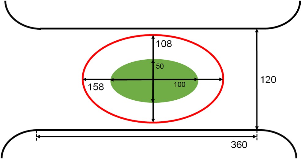
Gradient coils were designed for an open, compact MRI system that is used for hand imaging [1] (0.3 T Nd-Fe-B permanent magnet, gap = 12 cm, weight = 450 kg; Shin-Etsu, Chemical Co. Ltd, Tokyo, Japan). The target region was set to be a 150 mm x 150 mm x 50 mm diameter ellipsoidal volume (DEV) (Fig. 1). Oval coils (the ellipsoidal aperture = 220 mm (x) x 120 mm (z), 320 mm long) were designed using an inverse matrix method combined with a truncated singular value decomposition (TSVD) [2,3]. For comparison, biplanar coils (320 mm in diameter, 120 mm gap) were also designed.
In the TSVD calculation, the coil pattern was calculated through the superposition of the current potential eigendistributions generated from 65 (oval) and 18 (biplanar) eigenmodes chosen from low-ordered SVD modes with large singular values. The number of chosen modes were empirically determined in a way that the gradient inhomogeneity was around 10 %. The magnetic field at 1736 points in the target ellipsoid was evaluated. The current carrying surface had 15876 triangular finite elements and 8192 nodes. The design program was implemented using Visual C# and .NET Framework 4.5 in Microsoft Visual Studio Community 2013. The winding patterns were obtained by calculating the contour lines of the current potential, and the number of contour lines was 24.
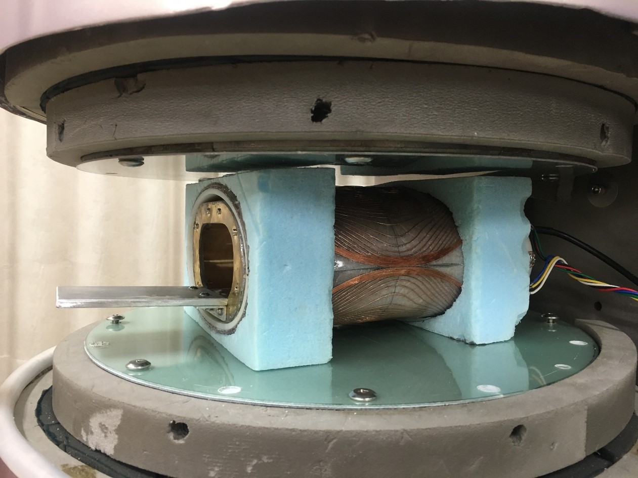
The designed oval gradients were constructed by winding a polyethylene-coated Cu wire (0.5 mm in diameter) and then fixed on plastic plates using epoxy resin. Then, the x, y, and z coil elements were stacked together and fixed on an acrylic cylinder (5 mm thick).
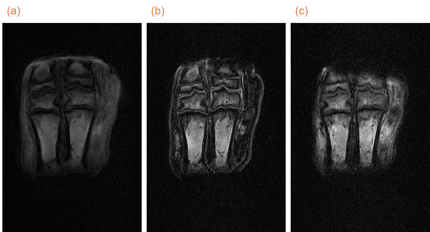
For demonstration, a forefoot of a pig was imaged using the oval gradients. The sequence used was three dimensional gradient echo with varying TE (TR = 40 ms; FOV = 10 cm x 15 cm x 5 cm; Matrix = 256 x 384 x 32).
RESULTS ANS DISCUSSION
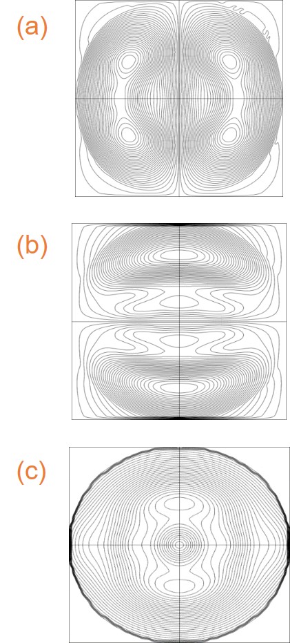
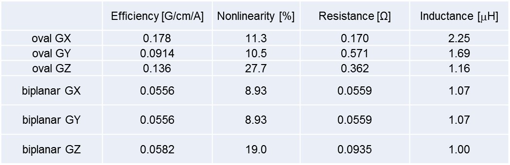
Figures 2 shows coil winding patterns for oval gradients. They have no overwrapping and no crossovers and it was easy to construct them. Table 1 summarizes comparison of theoretical performances of the oval gradients to the biplanar gradients. Overall, the oval gradients showed better performance; the efficiencies for the oval gradients were higher than those for the biplanar coils while the inductances were almost the same. However, the resistances were higher for the oval gradients than the biplanar coils. In general, there is a tradeoff between the efficiency, nonlinearity, and resistance. In the framework of the TSVD method, one cannot take a balance of these measures automatically, but should select the appropriate eigenmodes empirically to satisfy the desired performance. Here we chose the eigenmodes to maximize the efficiency, and this resulted in the high resistances of the designed coils. Coils with a lower resistance would be available by choosing the eigenmodes differently.
Figure 4 shows coronal slices of MR images. Imaging with a short TE (TE = 2 ms) was now possible, which could not be performed with the biplanar gradients because of the limited maximum gradient strength and slew rate.
CONCLUSION
We designed oval gradients for the vertical-field MRI system. It was revealed that the designed oval gradients exhibited the high performance.Acknowledgements
We would like to thank Dr. Mitsushi Abe for his helpful comments on the implementation of the TSVD code.References
[1] Y.
Terada et al., J. Magn. Reson. 230 (2013) 125-133.
[1] M. Abe et al., Phys. Plasmas, 10 (2003) 1022 -1033.
[2] M. Abe, IEEE Trans. Magn., 49 (2013) 5645 -5655.
Figures