4334
Design of an MRI Gradient Field Exposure System for Medical Device Testing1Physics and Astronomy, Western University, London, ON, Canada
Synopsis
A method to design and numerically optimize a gradient field exposure system for testing medical devices is presented. Magnet windings are modelled as small current elements in space, and dimensions of a coil capable of emulating the switching rate and strength of MRI gradient fields are chosen by a grid search of parameter space. A buildable option capable of achieving 1.2% homogeneity over an 8 cm DSV, a slew rate of 246 T/s, and a maximum field shift of 68 mT was determined to be sufficient for our application and for satisfying relevant elements of ISO/TS 10974.
Introduction
Rapidly switched gradient fields in MRI induce eddy-currents on implanted medical devices made of conductive materials. This can cause heating due to resistive losses, mechanical vibration, or device malfunction.1-3 For these reasons, medical devices require testing before they can be deemed MR conditional. Furthermore, testing in actual MR scanners can be impractical due to availability and expense, making the development of a separate gradient field exposure test platform desirable.
The relationship between the field at the centre of a thick solenoid of uniform current density and the resistive power is characterized by the Fabry factor:4 $$G(\alpha,\beta) = \sqrt{\frac{\beta}{2\pi(\alpha^2-1)}}\ln\frac{\alpha+\sqrt{\alpha^2+\beta^2}}{1+\sqrt{1+\beta^2}}$$ where $$$\alpha$$$ is the ratio of outer radius to inner radius of the coil, and $$$\beta$$$ is the ratio of the half length to the inner radius. It can be described as a field-power efficiency factor: $$B_0 = \mu_0\sqrt{\frac{P\lambda}{\rho a_1}}G(\alpha,\beta)$$ where $$$B_0$$$ is the field at the center of the coil, $$$P$$$ is the resistive power of the coil, $$$\lambda$$$ is a filling factor, $$$\rho$$$ is the resistivity and $$$a_1$$$ is the inner radius.
A third parameter, $$$\gamma$$$, is introduced here and is defined as the ratio of the half gap to the inner radius. This axial gap can improve homogeneity, similar to the concept of a Helmholtz coil.
Methods
Although coil design and optimization has been thoroughly investigated from an analytical perspective,5-7 our approach is numerical and models coils with discrete windings and an array of wire elements, using the Biot-Savart law as our fundamental equation for calculating magnetic field.8
An exhaustive grid search of parameter space $$$(\alpha,\beta,\gamma)$$$ was performed to provide understanding of the interactions between performance metrics such as the Fabry factor, homogeneity, slew rate, and maximum field shift. To further narrow down choices, an optimization of gamma was done that would achieve a target homogeneity of 2.5% or better over an 8 cm DSV, for a coil of 10 cm radius.
The candidate coils were further constrained by choosing a minimum field shift of 30 mT and minimum slew rate of 120 T/s. The final design decision was made from the coil that gives the best field uniformity with a field shift close to the lower bound, such that slew rate could be maximized.
Results
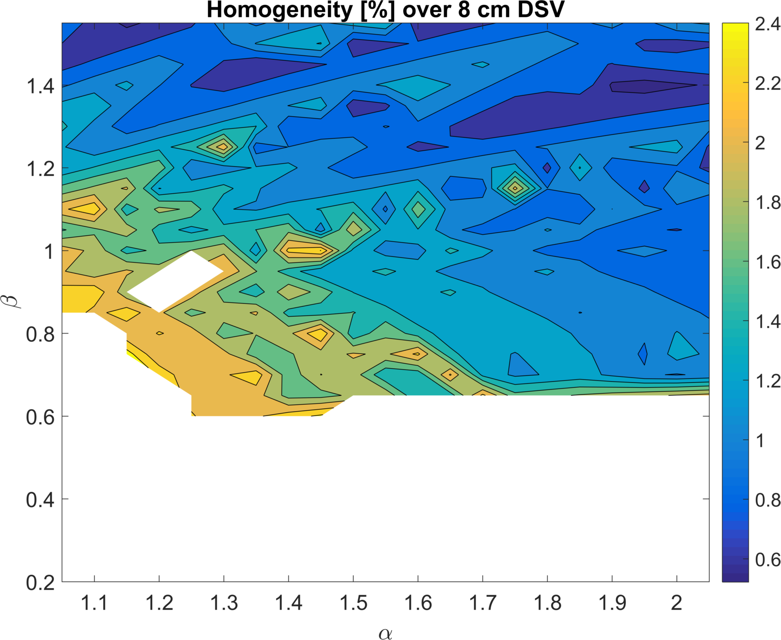
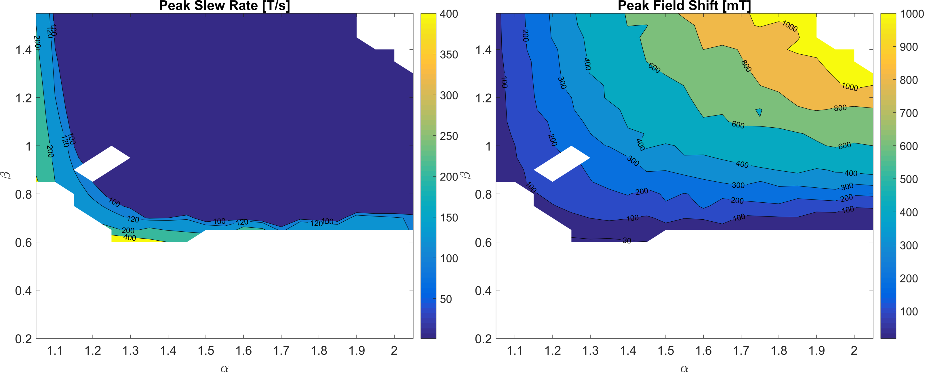
Figure 1 shows the best homogeneity that could be achieved by optimization of the axial gap, and figure 2 shows the corresponding slew rate and field shift assuming a 5 mm x 5 mm wire and a power supply of 350V and 430A. White space indicates regions where targets could not be met.
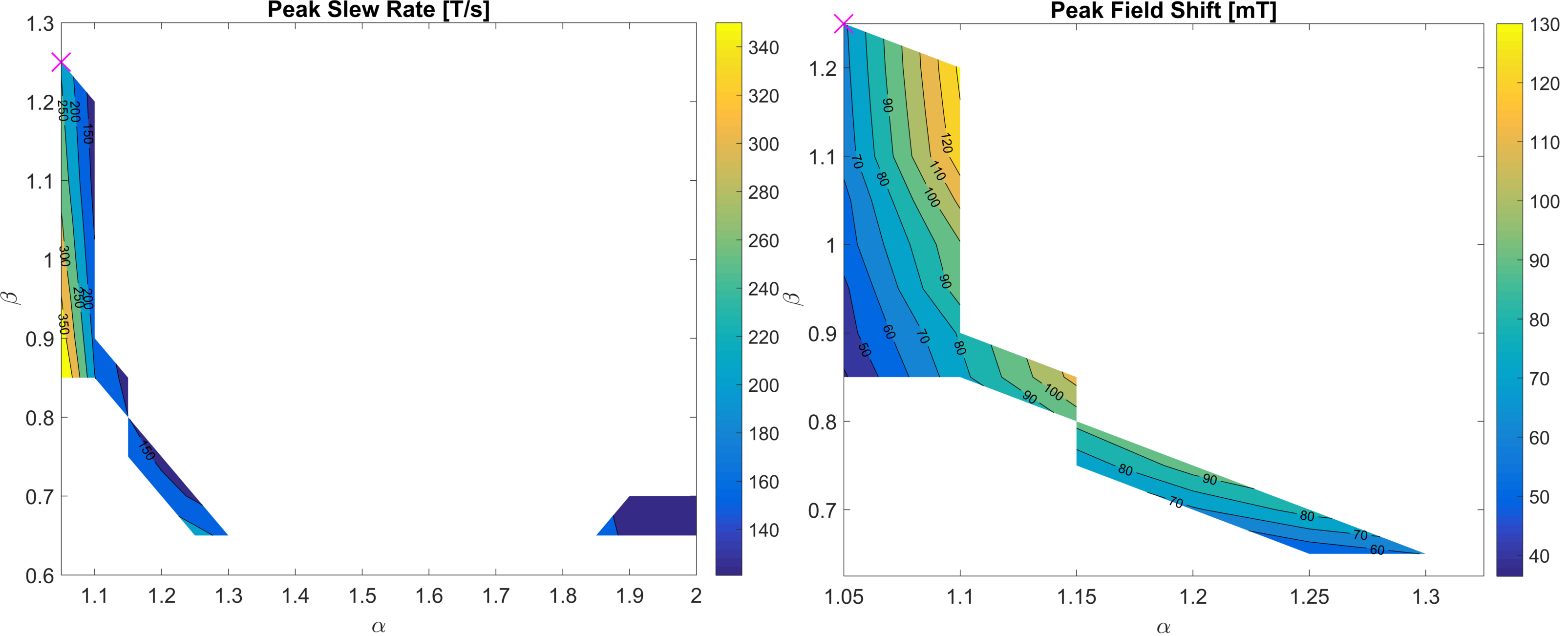
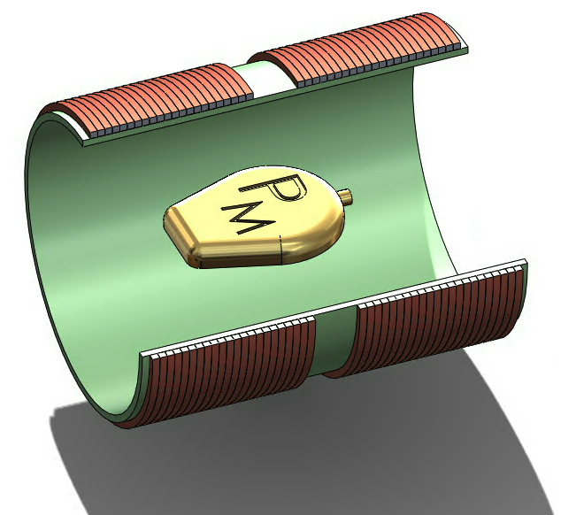
By applying the constraints to this parameter space only two allowable regions remained, from which a specific design was chosen due to its high field uniformity as well as values for slew rate and field shift that sufficiently satisfy ISO/TS 10974 (see figure 3).9 The Fabry factor in the left region is approximately two times that of the other, indicating better field-power efficiency. The coil properties are IR = 10 cm, OR = 10.5 cm, length = 25 cm, gap = 3 cm, axial windings = 44, and radial layers = 1. Homogeneity is 1.2% over a sphere 8 cm in diameter, with a peak slew rate of 246 T/s, and a peak field shift of 68 mT. Figure 4 shows a drawing this coil, with a sample pacemaker device in the testing region.
Discussion
An effective design tool for dB/dt systems has been demonstrated, that allows the selection of a candidate coil to build that meets application requirements. Typical MRI gradient systems produce peak field shifts of less than ±40 mT within the bore of the scanner. It is therefore not generally necessary to produce a dB/dt test platform of more than approximately 50% above this value.
This coil in particular was chosen because it had the best homogeneity and sufficiently met other targets. Secondary design considerations that could be included in the optimization are: cost of materials, thermal properties, force/torque, inclusion of inner/outer notches, and ease of construction. However, by greatly surpassing the target performance metrics of the application, it allows the freedom to make trade-offs as necessary when considering these other decisions.
Conclusion
We have demonstrated a capability to model the design of a solenoid coil that is optimized for testing medical devices. The coil presented is capable of gradient field exposure above that which is typically present in an MRI scan, and that also satisfies the requirements of ISO/TS 10974.9Acknowledgements
I would like to acknowledge the members of the xMR lab at Western University for their helpful contributions to this project. I also acknowledge NSERC: Industrial Research Chairs Program, Ontario Research Fund: Research Excellence Program, and the Canadian Foundation for Innovation for the funding required to complete this project.References
1. Hartwell RC, Shellock FG. MRI of cervical fixation devices: Sensation of heating caused by vibration of metallic components. Journal of Magnetic Resonance Imaging. 1997;7:771-772
2. Graf H, Lauer UA, Schick F. Eddy-current induction in extended metallic parts as a source of considerable torsional moment. Journal of Magnetic Resonance Imaging. 2006;23:585-590
3. KALIN R, STANTON MS. Current Clinical Issues for MRI Scanning of Pacemaker and Defibrillator Patients. Pacing and Clinical Electrophysiology. 2005;28:326-328.
4. Montgomery DB. Solenoid Magnet Design: The Magnetic and Mechanical Aspects of Resistive and Superconducting Systems. New York: Wiley-Interscience; 1969.
5. Turner R. Minimum inductance coils. Journal of Physics E: Scientific Instruments. 1988;21:948-952
6. Kabat D, Cesnak L, Kokavec J. Optimisation of inner-notch-corrected highly homogeneous superconducting solenoids and their comparison with other coil configurations. Journal of Physics E: Scientific Instruments. 1979;12:652-657.
7. Kratz R, Wyder P. Principles of Pulsed Magnet Design. New York;Berlin;: Springer; 2002
8. Turner, R. Gradient coil design: a review of methods" Magnetic Resonance Imaging. 1993;11:7: 903-920.
9. ISO/TS 10974. Requirements for the safety and compatibility of magnetic resonance imaging for patients with an active implantable medical device. www.ISO.org 2016
Figures