4333
Controlled E-peak field gradient coil1ARKFIELD PTY LTD, Brisbane, Australia, 2Medical Imaging Department, Suzhou Institute of Biomedical Engineering and Technology (SIBET), Suzhou, People's Republic of China, 3Division of Metrology for Quality of Life, Istituto Nazionale di Ricerca Metrologica (INRIM), Torino, Italy, 4Energia Department, Politecnico di Torino, Torino, Italy
Synopsis
This work presents a new shielding method capable to reduce E-peak field values by minimizing the infinite norm of the induced current density. The target volume (“organ”) is surrounded by a conductive surface “shell” where the infinite norm of the induced current density is minimized thereby producing a uniform distribution of the E-field inside the target volume and its surrounding. The method was effectively applied in the design of a whole body gradient coil with E-field control. E-field reduction larger than 10% are registered in a human phantom model. Further reductions in E-field is possible by compromising the coil performance.
Target Audience
This work will be of interest of those interested in the design of gradient coils with E-field control.Purpose
This work introduces an E-field controlled gradient coil design method based on the minimization of the infinite norm of the induced current density (min||Js||_infinity) on a target surface (s); which in this work is called the “shell” of a target organ. By min||Js||_infinity peak amplitudes of the E-fields are minimized thereby producing an uniform E-field in the target and surrounding organs. The method can also be considered as new shielding strategy for gradient coils where peak E-field/(or peaks of Js) must be avoided.Introduction
High strength and rapidly changing gradient fields may induce tingling sensations in the skin or even cardiac fibrillation. To counteract such undesirable effects, one strategy is to reduce the field linearity at the FoV, or reduce the size of target volume where the desirable gradient field is specified1. Head gradient coils have been used with some success but poor shielding and cumbersome access to the useful area of the FoV have limited the utilization of this type of coil. Another strategy is to reduce the strength and the rate of change of the magnetic field2. Few works have intended to modify the coil current pattern to reduce the induced E-field and thus the possibility of PNS occurrence3,4. This work presents a method where the infinite norm of the current density Js induced in a conductive surface “organ shell” is minimized thereby producing uniform distribution of Js5 in the “shell” and thus an uniform distribution of E-field inside the target region and its surrounding.Method
We assumed that the organ is covered by a conductive non-magnetic smooth and continues surface or conductive “shell” of constant electric conductivity σ, we also assumed that Js induced in the skin modifies the source magnetic field. In reality, the human tissues for frequencies smaller than 10kHz and typical conductivity of around 0.2 S/m are not a source of magnetic field. In this work however, the assumption of high conductivity is required as a mechanism to modify the coil current pattern.
Fig.1 describes an example of the application of the E-field control designing problem. The primary and shield coil domains are surrounded by a conventional 1.5T cold shield, the target RoI is a spheroid of 500x400 mm. Two additional symmetric domains s1 and s2 with center located at z=± 300 mm and dimension of 200mmx200mm are included as the “shell” of the target organ. The optimization is stated as min f(φ) subject to min||Js||_infinity≤j0(100-ρ)/100; in addition shielding, wire spacing, torque/force are also included. j0 is calculated in a preliminary optimization and it represents the maximal current density induced in the domains s1 and s2, respectively. φ is the unknown stream function. In this work, ρ was varied from 0 to 18. The coil with ρ=12 was selected and an additional coil with ρ=0 was designed to match the efficiency η of the coil with ρ=12. The residual eddy field was constrained to 0.65%, field non-linearity to 5.6%, the wire space was also constrained and the gradient strength was set to 33mT/m. The E-field was calculated in the DUKE model using 2 mm resolution at the frequency of 1kHz6.
Results and Discussion
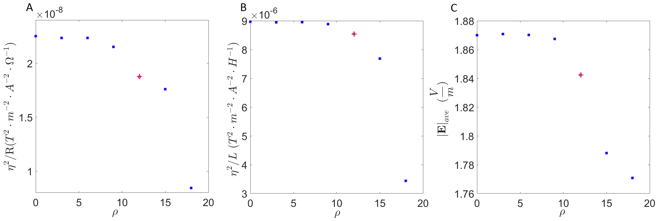
Fig.2 shows that the coil performance deteriorates when ||Js||_infinity in the domains s1 and s2 is restricted to lower values of j0 and as a consequence the average of the E-field, calculated in the volume7 (“organ” with σ=0.2 S/m) contained in the domains s1 and s2 also decreases. Fig.3, shows cartilage, liver and spinal cord for the coils ρ = 0 (A) and ρ=12 (B). A third figure (C) is the E-field produced by a coil that match the η of the coil ρ=12. The coil ρ=12 reduces the 99th percentile of E-field to values around and larger than 5% respect to the coil ρ=0 in the following tissues: heart muscle and lumen, cartilage, cerebellum, diaphragm, muscle, spinal cord, spleen. 10%-15%: Urinary bladder, gallbladder, large intestine, pancreas, stomach and stomach lumen. The worse E-field increment was registered in bone marrow with -3.2%. Tissues not mentioned here such as skin, SAT and skull shows no gain in E-field reduction. Fig.4, shows half of both coils ρ=0 and ρ=12.Conclusion
min ||Js||_infinity assures an uniform spatial distribution of Js in a target conductive domain thereby reducing E-peak values inside and around the surrounding the target domain. E-field reduction larger than 10% are registered in a human phantom model. Further reductions in E-field is possible by compromising the coil performance.Acknowledgements
No acknowledgement found.References
1. P.R. Harvey, The modular (twin) gradient coil—high resolution, high contrast, diffusion weighted EPI at 1.0 Tesla, Magnetic Resonance Materials in Physics, Biology and Medicine, 8 (1999) 43-47. 2. K. Setsompop, R. Kimmlingen, E. Eberlein, T. Witzel, J. Cohen-Adad, J.A. McNab, B. Keil, M.D. Tisdall, P. Hoecht, P. Dietz, Pushing the limits of< i> in vivo</i> diffusion MRI for the Human Connectome Project, Neuroimage, 80 (2013) 220-233. 3. P. Mansfield, B. Haywood, Controlled E-field gradient coils for MRI, Physics in medicine and biology, 53 (2008) 1811. 4. C.C. Sanchez, S.G. Garcia, H. Power, E-coil: an inverse boundary element method for a quasi-static problem, Physics in medicine and biology, 55 (2010) 3087. 5. M.S. Poole, P.T. While, H. Sanchez Lopez, S. Crozier, Minimax current density gradient coils: analysis of coil performance and heating, Magnetic Resonance in Medicine, 68 (2012) 639-648. 6. O. Bottauscio, M. Chiampi, J. Hand, L. Zilberti, A GPU computational code for eddy-current problems in voxel-based anatomy, IEEE Transactions on Magnetics, 51 (2015) 1-4. 7. M. Windhoff, A. Opitz, A. Thielscher, Electric field calculations in brain stimulation based on finite elements: an optimized processing pipeline for the generation and usage of accurate individual head models, Human brain mapping, 34 (2013) 923-935.Figures
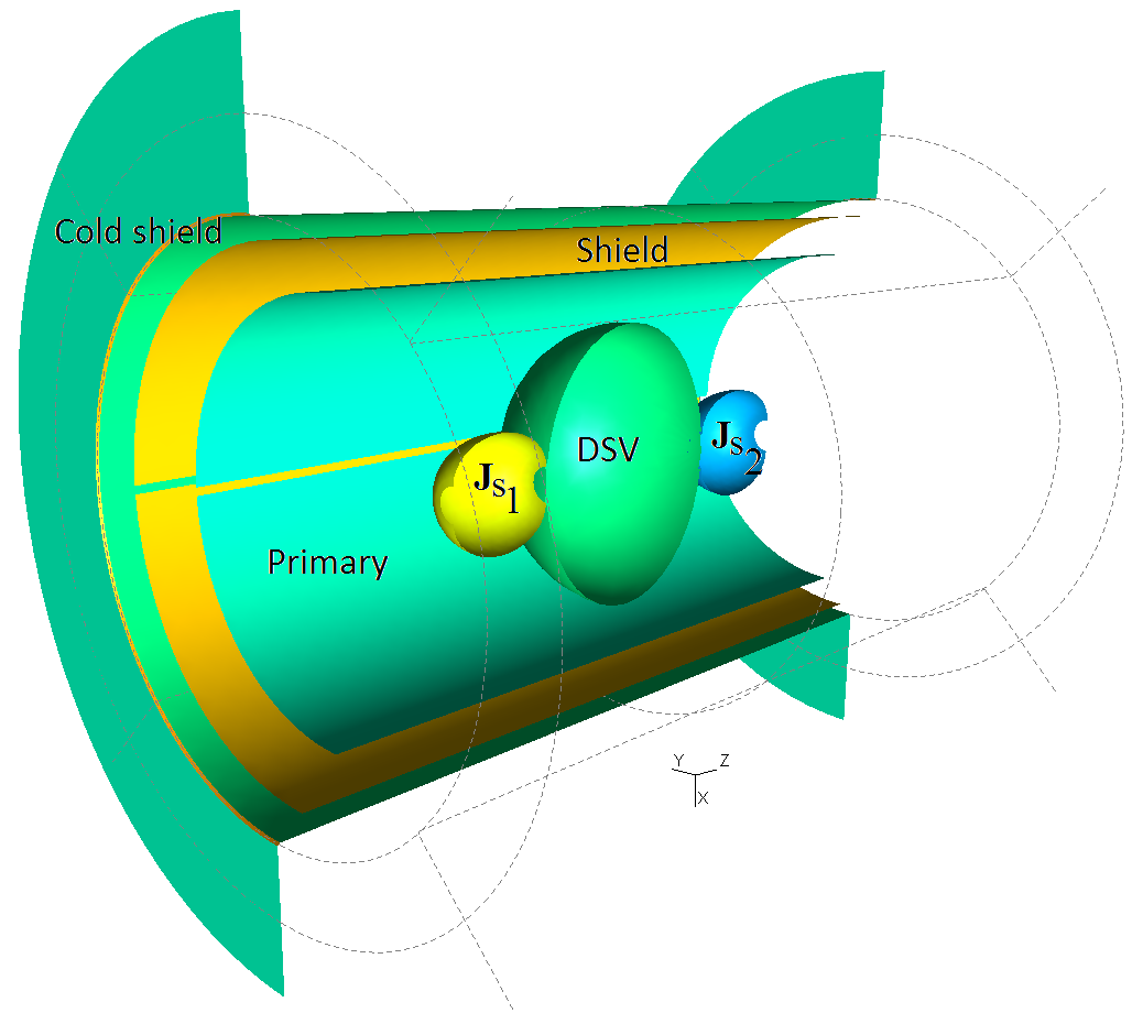
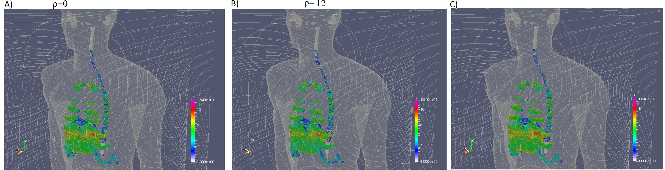
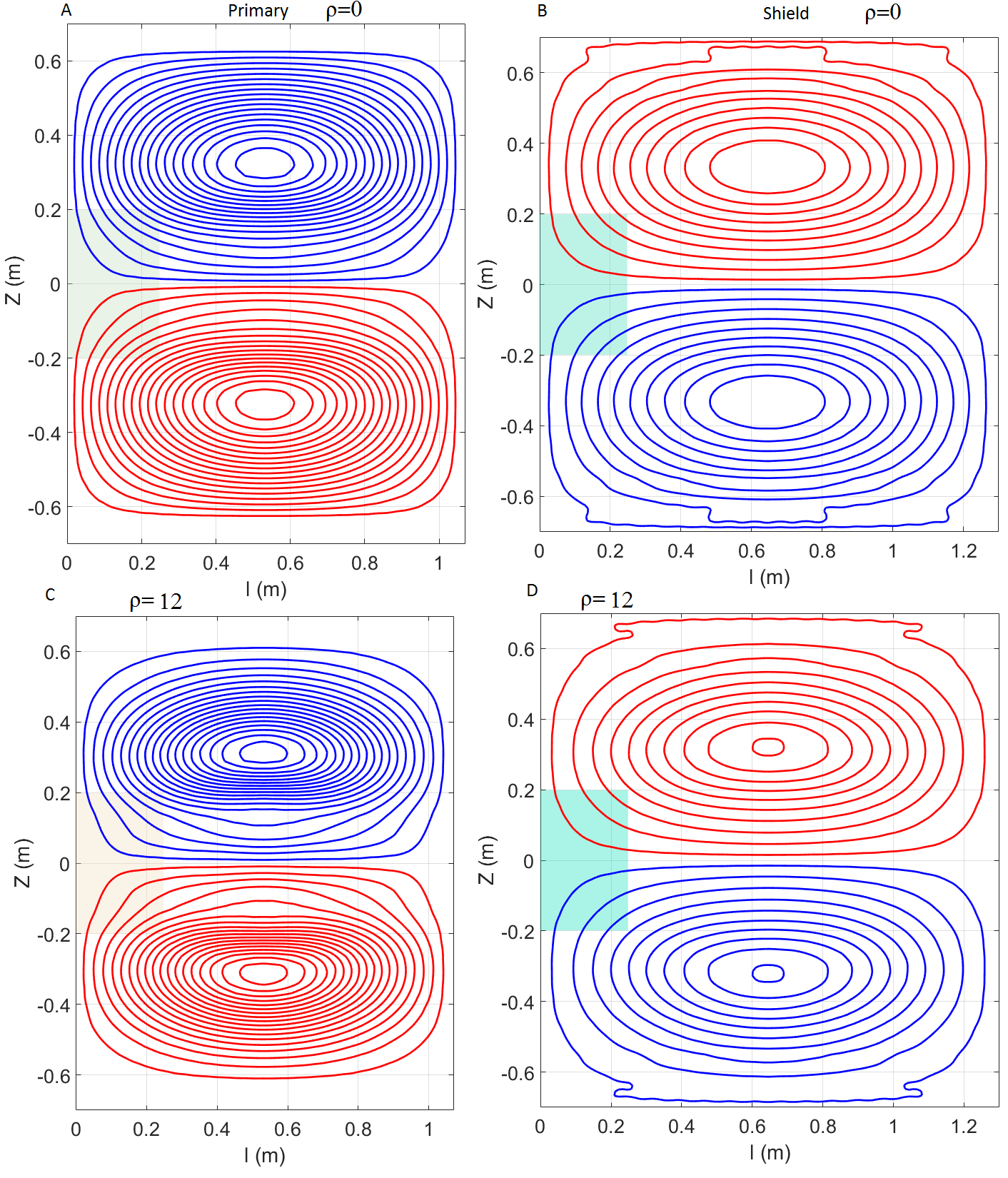
Fig.4 The coil ρ=12 yield an η=50μT/mA, an inductance of L=293 μH and resistance of R=134 mΩ. The slew rate was SR=122 T/m/s @600A and 800V. The rise time RT=256μs.
The coil ρ=0 yield an η=54μT/mA, L=325 μH and R=129 mΩ. The SR=120 T/m/s @600A and 800V. The RT=261μs.
The matching coil (no shown in this figure) with ρ=0 but not E-control yield an η=50μT/mA, L=298 μH, R=118 mΩ. The SR=120 T/m/s @600A and 800V. RT=259μs. The E-field of this coil was 20% higher than that optimized with E-field control (ρ=12).