4332
The numerical limitation of Multi-coil shim and Orthogonal RF-Shim coil1Institute of Biomedical Engineering, National Taiwan University, Taipei City, Taiwan, 2A. A. Martinos Center for Biomedical Imaging, Massachusetts General Hospital, Charlestown, MA, United States, 3Harvard Medical School, Boston, MA, United States, 4Department of Neuroscience and Biomedical Engineering, Aalto University, Espoo, Finland
Synopsis
We used numerical simulations to study the relationship between attainable field homogeneity and the number as well as the orientation of shim coils in a multi-coil shim array. We found
Purpose
Scientific and clinical applications of MRI require a highly homogeneous magnetic field (B0). The inhomogeneity of B0, can cause NMR signal reduction, MRI distortion, and MRS spectral line width increase.1 Localized shimming using multiple coils2, 3 has been demonstrated as a promising technology to reduce B0 inhomogeneity. It generates a compensating field to counter-act the off-resonance B0 measured by field mapping. Intuitively, more channels in a multi-coil (MC) shim array allows a higher degree of freedom in designing the shimming field.2 However, the performance gain is expected to be marginal when the number of the shim coil is beyond a certain number. Previous MC shimming only arranged coils by tessellating the surface of the imaging object by individual shim coils. 3,5-6 How the orientations of shim coils affect the shimming performance remains unexplored.
Here we attempt to answer this question by numerical analysis. Specifically, magnetic fields generated by up to 4401 shimming coils allowing for different orientations and positions on a brain surface were calculated to optimize the B0 homogeneity. At each shim coil location, up to three orthogonal shim coils were used to design the shimming current. Based on the simulation result, we propose a new RF-Shim coil design, where the shimming current path and the RF receiving coil are arranged on two different orthogonal planes.
Methods
Off-resonance field-maps were acquired from 9 healthy subjects. Forty slices of a dual-echo gradient echo images (2x2x2 mm3 voxel; TR = 10ms; TE1 = 2.00ms; TE2 = 4.46ms; Flip angle = 15°) were acquired on a 3T scanner (Skyra, Siemens, Erlangen, Germany) after applying the system’s second-order Spherical Harmonic (SH) global shimming. An off-resonance field map was calculated by measuring the phase accrued between two TE’s at each voxel 7. An average off-resonance field-map, was created by first morphing individual’s off-resonance map on a common coordinate system and then averaging across subjects.
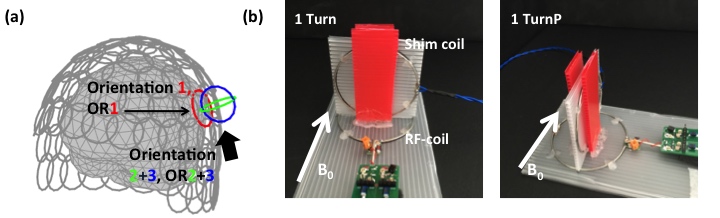
The magnetic field from each circular shimming coil was calculated by the Biot-Savart’s law. Shimming coil positions were restricted on a close-fitting helmet surface. Three MC arrays with 102, 380 or 1467 coil positions were simulated. At each shim coil position, we allowed three orthogonal planes to place the shim coil. One plane (Orientation1, OR1) has the normal direction of the coil plane at the center of the shim coil pointing toward the center of the FOV center (the imaging object was placed at the center of the FOV). The other two orthogonal coils planes were referred to as orientation 2 and 3. The radius of each shim coil was adjusted to cover the helmet surface (20, 10 or 5mm). Definitions of shim coil orientations and examples of shimming arrays were shown in Fig.1a. The standard deviation of B0 (σB0) within the whole imaging object was calculated to assess the performance of shimming.
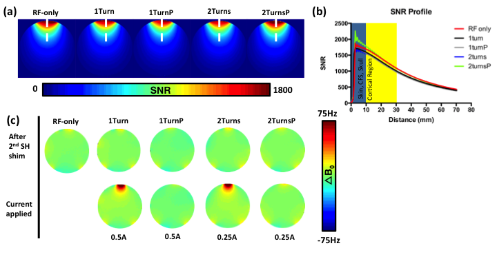
Our RF-shim coil was based up on a conventional circular receiver coil, and the shim current plane was perpendicular to the RF coil plane. The normal direction of the shim coil plane was either in parallel (1TurnP or 2TurnsP) or perpendicular (1Turn or 2Turns) to B0 (Fig.1b). SNR maps were separately measured for an RF coil and modified RF-Shim coils using a GRE sequence (0.7x0.7x5mm3; TR = 462ms; TE = 10ms; Flip angle = 25°). The coil noise map was measured by using the same sequence with the flip angle set to 0 degree. Coil field-maps were acquired using the same dual-echo GRE mentioned above. All RF-shim coils shared the same circular receiver coil.
Result
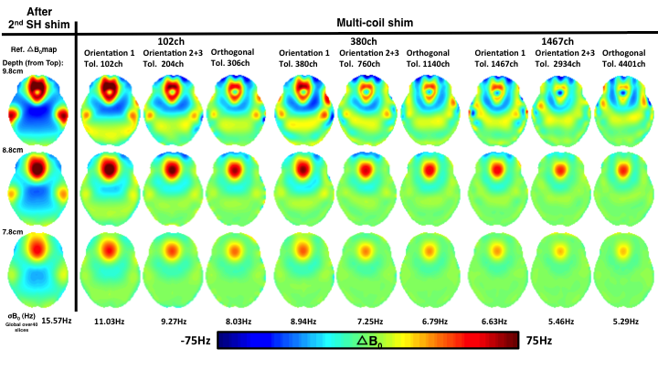
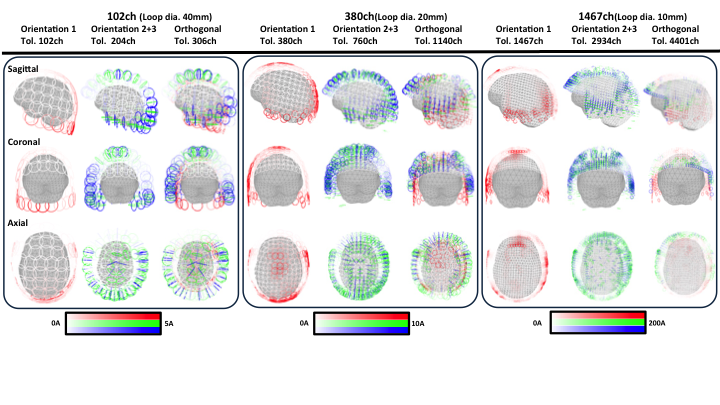
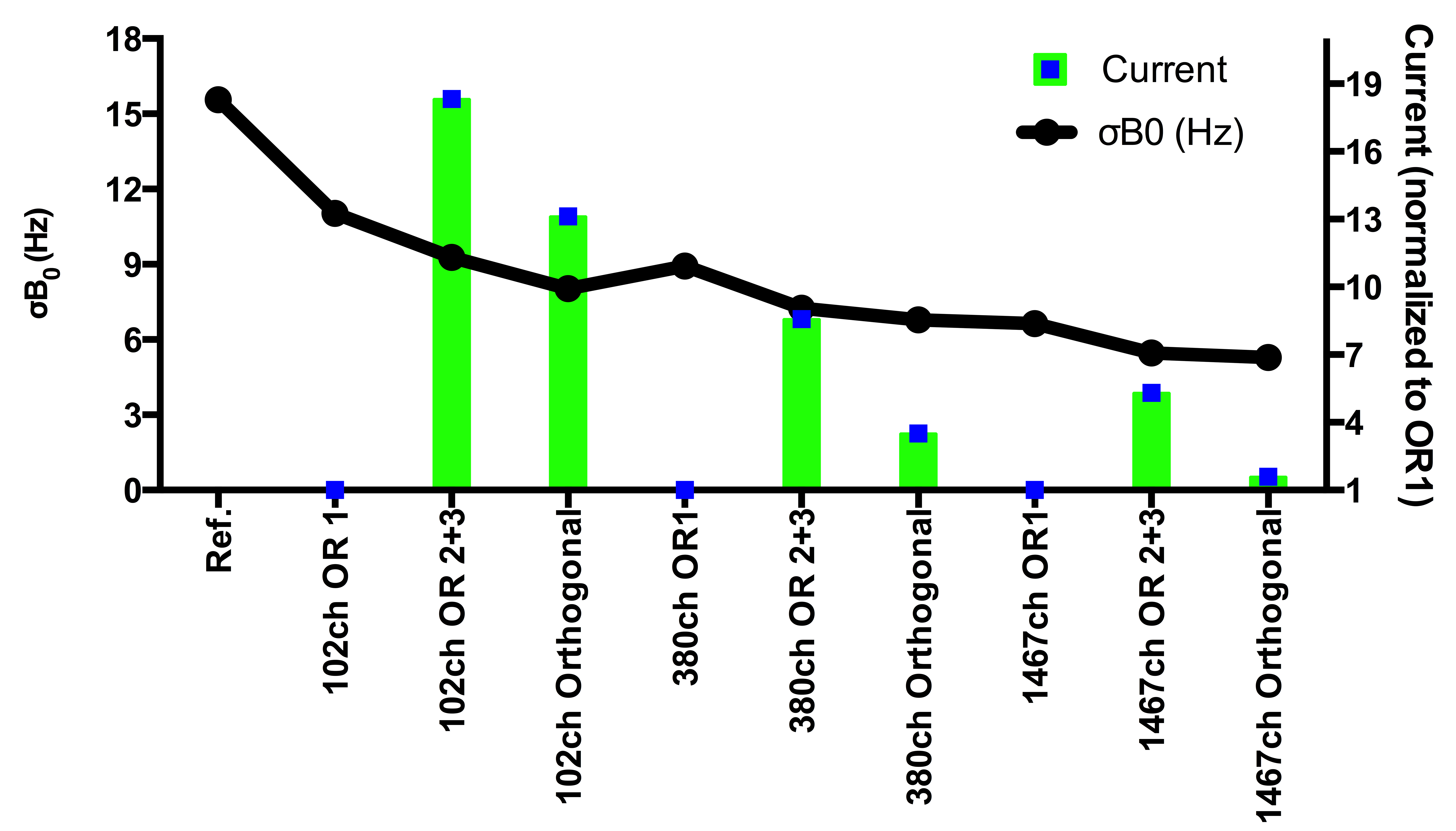
The Fig.2 to 4 summarize the performance of MC shim arrays. Increasing the number of channels led to improved shimming. The combination of OR 2 and 3 can improve field homogeneity compared with OR1. Fig.3 shows the current distribution of different combination. Fig.2 and 4 show the simulated shimming performance of nine shim array geometries. Fig.4 also shows the shim current required for shim geometries. Fig.5 shows the SNR map, the SNR profiles of different coils at different distance from the coil center and the B0 field-map. Our RF-Shim coil exhibits less SNR loss as well achieves multi-turn shim coil design to minimize required shim current.Discussion
Simulations show that better shimming can be obtained by using more coils in a shim array. Using the OR2+3 combination for shim could achieve similar shimming performance compare with orthogonal design but required a higher current. However, by using multi-turn shim coil, we could maintain the shim current in an acceptable number. The SNR loss of our RF-Shim coil is less than previous report.6Acknowledgements
This work was partially supported by Ministry of Science and Technology, Taiwan (103-2628-B-002-002-MY3, 105-2221-E-002-104), and the Academy of Finland (No. 298131). The authors thank Lawrence L. Wald, Jhy-Neng Tasso Yeh and Zhe Wu for helpful discussion.References
1. Koch K M, Rothman D L, de Graaf R A. Optimization of static magnetic field homogeneity in the human and animal brain in vivo. 2009, 54(2): 69- 96.
2. Juchem C, Nixon T W, McIntyre S, et al. Magnetic field modeling with a set of individual localized coils. J Magn Reson, 2010, 204(2): 281-289
3. Juchem C, Nixon T W, McIntyre S, et al. Dynamic multi-coil shimming of the human brain at 7T. J Magn Reson, 2011, 212(2): 280-288.
4. Juchem C, Nixon T W, McIntyre S, et al. Magnetic field homogenization of the human prefrontal cortex with a set of localized electrical coils. Magn Reson Med, 2010, 63(1): 171-180
5. Juchem C, Rudrapatna S U, Nixon T W, et al. Dynamic multi-coil technique (DYNAMITE) shimming for echo-planar imaging of the human brain at 7 Tesla. NeuroImage, 2015, 105: 462-472.
6. Stockmann J P, Witzel T, Keil B, et al. A 32-channel combined RF and B0 shim array for 3T brain imaging. Magn Reson Med, 2015, 75(1): 441-451.
7. Irarrazabal P, Meyer C H, Nishimura D G, et al. Inhomogeneity correction using an estimated linear field map. Magn Reson Med, 1996, 35(2): 278-282.
Figures