4330
Global and dynamic shimming with the scanner’s inbuilt shim system and a custom-made multi-coil setup at 9.4 T1Max Planck Institute for Biological Cybernetics, Tübingen, Germany, 2IMPRS for Cognitive and Systems Neuroscience, University of Tübingen, Tübingen, Germany, 3Department of Biomedical Magnetic Resonance, University of Tübingen, Tübingen, Germany
Synopsis
The homogenization of static magnetic field (B0) is necessary for MR imaging. The unwanted B0 inhomogeneity becomes more pronounced in ultra high field, and the scanner's inbuilt shim setup can not compensate the B0 fluctuation as is needed. Here we propose to use combined setup of the multi-coil approach and the scanner's shim setup to achieve higher homogeneity of B0 field. We employed custom-built multi-coil for slice-wise shimming in combination with the scanner's shim setup for global shimming. The results show improvement about 50% compare to dynamic shimming alone in the most of the slices.
Introduction
The homogeneity of the main static magnetic field (B0) is a crucial prerequisite for MR imaging due to the manifold image artifacts that can arise from field perturbations. The initially homogeneous B0 field inside the empty magnet bore is distorted by the insertion of a human subject. This B0 inhomogeneity becomes more pronounced with increasing field strength and can lead to severe image distortions 1. Usually, the scanner’s inbuilt shim system, which creates spherical harmonic (SH) field terms, is used for global static shimming. Recently, smaller local coils were proposed in the literature to achieve a higher shim performance 2. However, it remains difficult to shim large volumes efficiently. Slice-wise dynamic shimming can mitigate this problem as field distortions in a much smaller sub-volume have to be compensated 3. Here we propose to combine global shimming with the scanner’s SH shim system and dynamic shimming with a custom-made multi-coil setup to achieve a superior homogeneity of the B0 field.Method
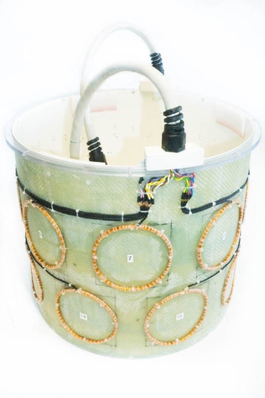
A multi-coil shim setup was constructed consisting of 16 circular coils, which were arranged in two rows. Each coil had 25 wire turns and a diameter of 100 mm. The coils were mounted on a fiber-glass cylinder having a diameter of 370 mm and a length of 310 mm. The prototype of this multi-coil setup is illustrated in figure 1. A custom-built amplifier was used to drive the 16 coils individually. The setting for proportional–integral–derivative (PID) controller of the amplifier could be adjusted for each individual coil in order to get the best performance for rapid switching with the least overshoot in the output current. The voltage induced by gradient switching limited the maximum number of wire turns for the B0 coils. The maximum output of the amplifier was limited to 2 A per channel to prevent excessive heating of the shim setup. Communication with the amplifier was conducted with an analog signal generated by a 16-bit digital-to-analog converter (DAC). A custom-built LABVIEW (National Instruments, Austin, TX) program was responsible for driving the DAC. To evaluate the performance of the amplifier and the multi-coil setup, we used a double-echo gradient echo sequence to create B0 maps before and after shimming a large cylindrical phantom filled with silicon oil. The MR sequence was modified to be able to send the next slice number to be measured to LABVIEW via a standard UDP protocol. In this way, the slices could be excited and measured in any arbitrary order. We employed a two-channel antenna as RF transceiver to get larger FOV, and the measuring protocol for the gradient sequence was as following: TE1/TE2/TR: 2.04/3.84/20 ms, Slices: 25, FOV: 300x300x90 mm3. The measurement was repeated five times: 1- without any shimming to get the initial B0 map, 2- after global shimming with the scanner’s SH shim system on the data acquired in 1, 3- after global shimming with the multi-coil setup on the data acquired in 1, 4- after dynamic shimming with the multi-coil setup on the data acquired in 1 and 5- after global shimming with the scanner’s SH shim system after which the multi-coil dynamic shimming was performed. The required amperage for each individual coil and slice was calculated using the fmincon function in MATLAB. More precisely, a linear combination of the fields generated by the B0 coils was determined that approximated best the acquired B0 map before shimming.Results
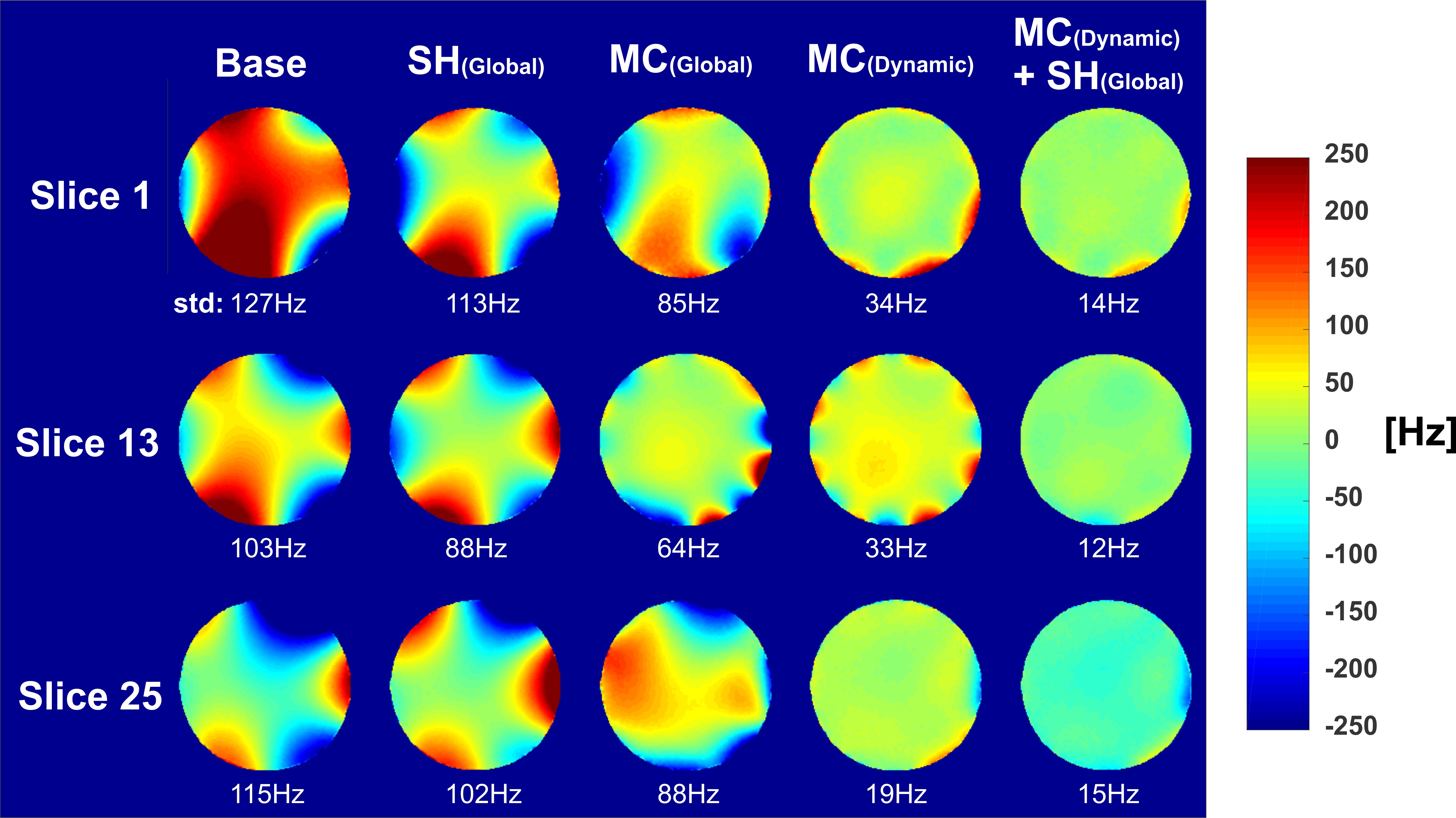
Figure 2 shows a comparison of the B0 field distribution for three slices from the aforementioned measurements. The standard deviation of B0 field is stated for each slice and measurement as well. The outer slices exhibited the highest improvement. The calculated currents did not exceed 1 A for any slice, even though an upper bound of 2 A was set in the optimization.Discussion & Conclusion
In this study, different shimming strategies were compared. For removing the smooth variations in B0 field, the scanner’s SH shim system works nice, while for the local stronger inhomogeneity, multi-coil approach can perform better. To date, no shimming method exists that compensates B0 inhomogeneity perfectly for all situations, therefore the combined method can bring strengths together. According to the results, the combination of dynamic and static SH shimming improves B0 homogeneity by about 50% compared to dynamic shimming alone in the most of the slices. Similar results are expected in the case of in-vivo measurements.Acknowledgements
No acknowledgement found.References
1. S. Sengupta et al., “Dynamic B0 shimming at 7 T,” Magn. Reson. Imaging, vol. 29, no. 4, pp. 483–496, 2011.
2. C. Juchem, T. W. Nixon, S. McIntyre, D. L. Rothman, and R. A. De Graaf, “Magnetic field modeling with a set of individual localized coils,” J. Magn. Reson., vol. 204, no. 2, pp. 281–289, 2010.
3. K. M. Koch, S. McIntyre, T. W. Nixon, D. L. Rothman, and R. A. de Graaf, “Dynamic shim updating on the human brain,” J. Magn. Reson., vol. 180, no. 2, pp. 286–296, 2006.
Figures