4329
A lightweight gradient insert coil for high resolution brain imaging1Radiology, University Medical Center Utrecht, Utrecht, Netherlands, 2Futura Composites B.V., Heerhugowaard, Netherlands, 3Spinoza Center for Neuroimaging, Amsterdam, Netherlands
Synopsis
A lightweight insert gradient coil was constructed for high resolution brain imaging. The coil was designed as a single-axis unshielded coil to accelerate EPI readouts. The resulting coil weighs 45 kg and can be quickly positioned in the scanner by two persons. Theoretically, a gradient strength of 210 mT/m can be achieved with a slew rate of 1088 T*m-1*s-1 when driven at 400V/600A. In a 7 tesla scanner, an efficiency of 0.35 mT*m-1*A-1 with a slew rate of 800 T*m-1*s-1 was measured. Experiments on five healthy volunteers resulted in no experiences of nerve stimulation.
Purpose
Functional brain imaging at mesoscopic scale (~0.5 mm) is crucial for a better understanding of the brain because at this scale neuronal ensembles form cortical microcircuits. As of yet, these microcircuits have only been studied in animals with invasive neurophysiological measurements1. The possibility of non-invasive imaging of these microcircuits in humans using MRI would be an important tool for studying both healthy and diseased brain. Key to the solution is to exploit the high inherent sensitivity and specificity of functional MRI at ultra-high field (7T) MRI. Recent advances in obtaining highest spatiotemporal resolutions have mainly focused on improving the signal detection capabilities, i.e. dedicated receiver arrays. However, the full potential and optimal use of these approaches is currently largely restricted by limitations of whole body gradient systems. For this purpose, we have developed a lightweight single-axis head gradient insert coil prototype with a modular insertable transmit coil, and allows the usage of a standard 32-channel receive coil for 7T (Nova Medical).Methods
The insert gradient device was designed as a z-gradient only device, with an inner diameter of 33 cm. The gradient coil consists of 12 Maxwell pairs, where the optimal winding positions were determined using a genetic algorithm global optimization approach with an objective function targeting high efficiency, linearity (over 16 cm) and low inductance. Shielding of the gradient was omitted in order to keep the device lightweight. This first prototype was constructed by Futura Composites B.V., Heerhugowaard, the Netherlands.
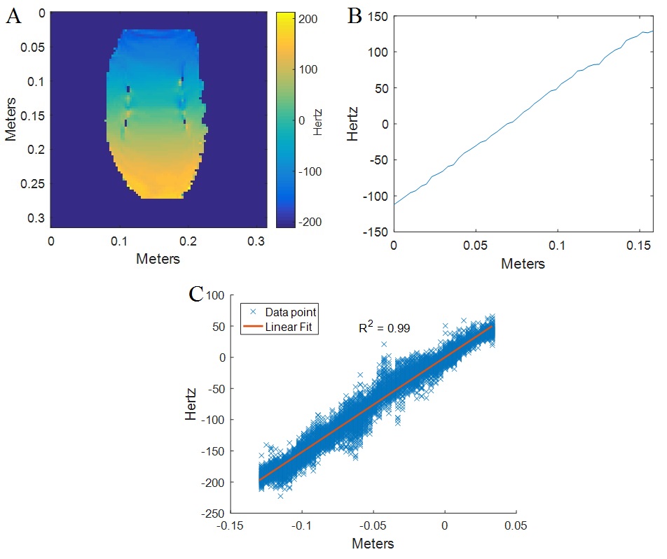
Inductance and resistance, including cabling and the power feed through filters of the faraday cage, were measured at 1 kHz using a LCR meter (Keysight Technologies). The gradient coil was positioned inside a Philips 7T MRI and connected to a Copley 271 gradient amplifier (400 V, 600 A). Gradient coil efficiency and field linearity was assessed over a range of 16 cm using a B0 map of a phantom bottle (length 30 cm) while providing 0.1 A of current. Three gradient fields (X,Y,Z) were fitted to the B0 map after correction and from this the gradient coil efficiency in the Z-direction was determined. The obtained efficiency was then used to calculate the maximum achievable gradient strength for the used gradient amplifier.
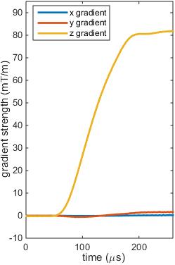
The theoretical maximum slew rate was calculated using $$$SR = \frac{U-I*R}{L}*η $$$, where U, I, R, L and η denote the measured voltage, current, resistance, inductance and efficiency respectively. To confirm the slew rate, nine field cameras (Skope magnetic resonance technologies, Zürich, Switzerland) were positioned in the gradient coil, while switching the coil from 0 mT/m to 80 mT/m in 100 µs.
To assess nerve stimulation, five healthy volunteers were subjected to the maximum slew rate in a rise time of 200 µs.
Results
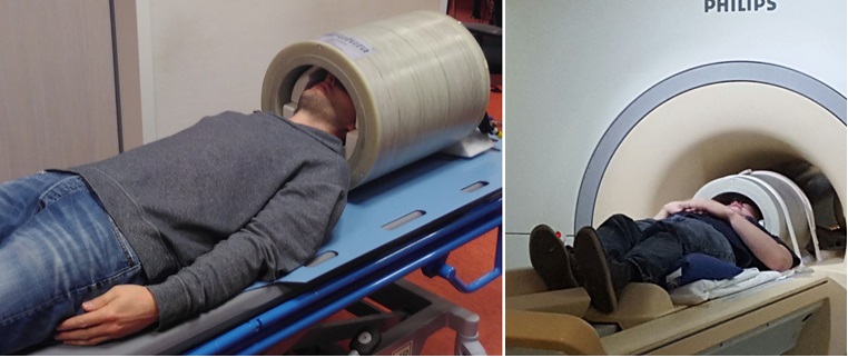
The constructed gradient coil (figure 1) has a weight of 45 kg and can be positioned in the system by two persons without the use of additional tools. The inductance is 113 µH and the resistance 81 mΩ. The efficiency of the coil was 0.35 mT*m-1*A-1, and the linearity has an R2 of 0.99.
With the used amplifier, the theoretical maximum achievable gradient strength is 210 mT/m, with a slew rate of 1088 T*m-1*s-1.
The measured slew rate was approximately 800 T*m-1*s-1 (figure 3). During the switching, a small y-gradient (<2% of z-gradient) was measured as well.
None of the volunteers experienced nerve stimulation when pulsing the gradient coil.
Discussion
A lightweight high efficiency insert gradient coil prototype was constructed. This gradient coil can enable high resolution fMRI imaging, while, at the same time, positioning the coil in the system remains easy.
Active shielding was omitted to reduce the weight of the coil. This means the coil will inductively couple to the cryostat, creating eddy currents in the cryostat. It is expected that, when driving the insert gradient coil in synergy with the whole-body gradient coils, these eddy currents can be compensated2. The maximum achievable slew rate of the in-bore experiments did not completely match the theoretical maximum attainable slew rate. This may be caused by the gradient amplifier PID settings, which were not matched yet to the specific characteristics of the gradient coil.
Acknowledgements
No acknowledgement found.References
1. Wozny C, Williams SR. Specificity of synaptic connectivity between layer 1 inhibitory interneurons and layer 2/3 pyramidal neurons in the rat neocortex. Cereb. Cortex. 2011;21:1818–26.
2. van der Velden TA, van Houtum Q, Gosselink MJM, Luijten PR, Boer VO, Klomp DWJ. Characterization of a breast gradient insert coil at 7 tesla with field cameras. In: International society of magnetic resonance in medicine. ; 2016. p. 3543.
Figures