4327
A comparative study of coil winding techniques of a full body 1.5 T MgB2 based MRI magnets.1Mechanical & Aerospace Engineering, Case Western Reserve University, Cleveland, OH, United States, 2Department of Physics, Case Western Reserve University, Cleveland, OH, United States
Synopsis
Control of strain development in an MgB2 based full body MRI magnet is a challenge towards realizing a conduction cooled system. It is possible to alter the strain development in an MRI magnet by modifying the coil winding support conditions and by varying the winding stress on the wire across the layers. A multiscale multiphysics model is employed to study the strain comparison by varying support conditions and winding prestress. Results conclude, radial support with constant winding prestress generates about 50% less stress and 42% less strain compared to no mandrel support.
Introduction
Due to the high sensitivity to strain of MgB2 wires,1 designing MRI magnet systems whereas strain development is kept minimum is of utmost importance. The electromagnetic designs of such magnets have been published and are used in this study.2 Also, methods to estimate the strains and stress at electromagnetic excitation stage has been developed. Implementing multiscale and multiphysics techniques for a composite MgB2 wire reports ~0.06% of strain development according to a prior study.3 However, it is possible to alter the strains more by changing support condition during winding4,5 or by varying the winding pretension on the wires for each winding layers.6 Thus this novel investigation will provide insights into the strain scenario of the magnets as allowing more room for strain development during quench.5,7–9 Numerical homogenization techniques10,11 are preferred over the rule of mixture techniques12 since they more accurately represent the behavior of the composite wire. Therefore, this multiscale multiphysics model is used to calculate the stress and strain development with different winding pretension and support conditions and assist with design safety as quench is concerned.13,14 In this study, the focus is on calculating the total strain after the magnet has been wound, cooled, and energized, and the effect of winding stress variation and mechanical support conditions on this strain.Methods
Electromagnetic designs and coil dimensions of MRI magnets are optimized according to methods detailed by Baig et al.2 A schematic of the system is presented in figure 1. A cross section of the 18 filament MgB2 wire obtained from Hypertech Research Inc is shown in figure 2. The wire is modeled in a CAD software and imported into the commercial finite element analysis (FEA) program ANSYS. Numerical homogenization of the orthotropic model is performed according to techniques described by Barbero10 and Boso15,16 and the results are summarized in figure 3. The homogenized wire is then used to model the winding, cool-down and electromagnetic charging of a coil as detailed elsewheare.3 In this work, the 1st principal strains (an important limit in the MgB2 wire), and the maximum shear stresses (an important limit in the coil epoxy) are considered. Four different types of support conditions are considered: i) Without supporting mandrel, ii) Radial Supporting mandrel, iii) Radial and axial supporting mandrel, and iv) Axial supporting mandrel only. During the coil winding, the applied wire pretension could be kept constant, or could be varied linearly, logarithmically, or exponentially with the layer number as winding progresses with pretension magnitudes in the range of 1 MPa to 31 MPa.Results
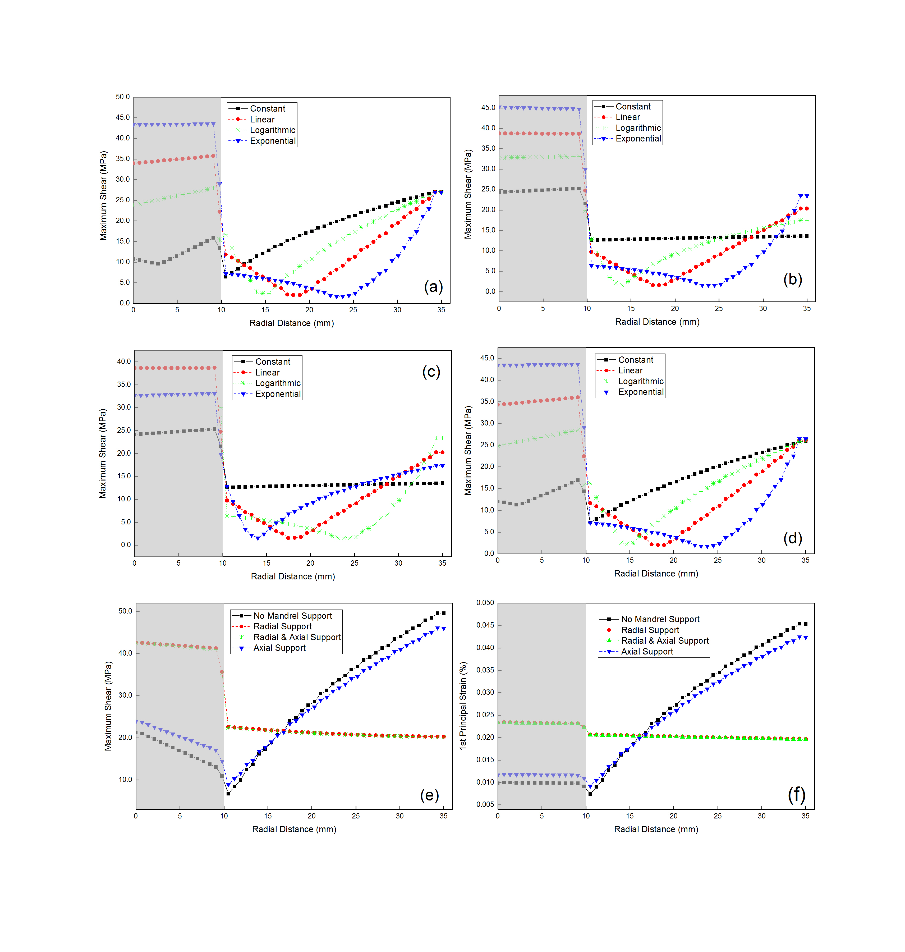
For each winding scenario, the calculated 1st principal strain (after winding, cool-down to 10 K operating temperature, and electromagnetic excitation to operating current density of 118.5 A/mm2) is shown in Figure 4. The strain is minimized when a radial support is employed, and a constant 31 MPa winding stress is applied during winding (Figure 4 (b)). In this case, the maximum strain 0.019%. Crack in epoxy due to excess shear stress is another cause of magnet failure. Figure 5 shows the maximum shear stress variation in bundle 5. The maximum shear has a minimal value of 13.6 MPa when the radial support is employed. This is the same support that minimizes the strains. Figure 5 (e) and (f) shows the effect of different support conditions on the stress and strain.Discussion
Composite superconducting wire made of MgB2 is resilient up to a strain value of 0.4%.1 When considering a conservative design, the failure criteria is 0.2%. Also the epoxy used in the magnet manufacturing has failure strength of ~50 MPa17. Therefore, it is important to keep the strain and stress development as low as possible. Numerical simulation results indicate both stress and strain is low if radial support with constant pretension is provided during winding.Conclusion
This study considered a multiscale-multiphysics model of a full body 1.5 T MRI magnet designed by composite 18 filament MgB2 wire. Study found that using a radial support with constant pretension during magnet winding generates lowest possible stresses and strains which is about 50% of 1st principal strain in MgB2 and 42% of maximum shear stress in epoxy.Acknowledgements
This work was supported partly by the National Science Foundation Partnerships for Innovation: Building Innovation Capacity (PFI: BIC) subprogram under Grant No. 1318206, Ohio Third Frontier and Ohio Development Services Agency.References
1. Kovác, P. et al. Behaviour of filamentary MgB2 wires subjected to tensile stress at 4.2 K. Supercond. Sci. Technol. 26, 105028 (2013).
2. Baig, T., Yao, Z., Doll, D., Tomsic, M. & Martens, M. Conduction cooled magnet design for 1.5 T, 3.0 T and 7.0 T MRI systems. Supercond. Sci. Technol. 27, 125012 (2014).
3. Amin, A. A. et al. A multiscale and multiphysics model of strain development in a 1.5 T MRI magnet designed with 36 filament composite MgB2 superconducting wire. Supercond. Sci. Technol. 29, 55008 (2016).
4. Amin, A., Baig, T. N., Deissler, R. J., Akkus, O. & Martens, M. Effect of mechanical support conditions of winding on the strain development of a composite MgB2 based full body MRI coil. in (ASC, 2016).
5. Li, L. et al. Effect of Pretension, Support Condition, and Cool Down on Mechanical Disturbance of Superconducting Coils. IEEE Trans. Appl. Supercond. 22, 3800104–3800104 (2012).
6. Arp, V. Stresses in superconducting solenoids. J. Appl. Phys. 48, 2026–2036 (1977).
7. Li, L. et al. Preliminary Mechanical Analysis of a 9.4-T Whole-Body MRI Magnet. IEEE Trans. Appl. Supercond. 25, 1–7 (2015).
8. Dai, Y. et al. Structural Design of a 9.4 T Whole-Body MRI Superconducting Magnet. IEEE Trans. Appl. Supercond. 22, 4900404–4900404 (2012).
9. Chen, J. & Jiang, X. Stress Analysis of a 7 T Actively Shielded Superconducting Magnet for Animal MRI. IEEE Trans. Appl. Supercond. 22, 4903104–4903104 (2012).
10. Barbero, E. J. Finite Element Analysis of Composite Materials Using ANSYS®, Second Edition. (CRC Press, 2013).
11. Amin, A. et al. Variation in strain characteristics for multiscale multi-physics models of a 1.5T conduction cooled MRI system based on a 36 filament MgB2 composite wire. in (ISMRM, 2016).
12. Amin, A., Baig, T. N., Yao, Z. & Martens, M. Stress and Strain Sensitivity Study of 1.5T Conduction Cooled MgB2 Magnet Design. in (ISMRM, 2015).
13. Poole, C. et al. Numerical study on the quench propagation in a 1.5 T MgB2 MRI magnet design with varied wire compositions. Supercond. Sci. Technol. 29, 44003 (2016).
14. Deissler, R. J. et al. Numerical Simulation of Quench Protection for a 1.5 T Persistent-Mode MgB2 Conduction-Cooled MRI Magnet. Supercond. Sci. Technol. accepted for publication, (2016).
15. Boso, D. P. A simple and effective approach for thermo-mechanical modelling of composite superconducting wires. Supercond. Sci. Technol. 26, 45006 (2013).
16. Boso, D. P., Lefik, M. & Schrefler, B. A. Homogenisation methods for the thermo-mechanical analysis of Nb3Sn strand. Cryogenics 46, 569–580 (2006).
17. http://ncsx.pppl.gov/NCSX_Engineering/Materials/InsulationProperties/CTD-101K_Datasheet_2003.pdf.
Figures