4325
Initial tests of a 4-channel building block for a local 32-channel Rx-only body coil at 7T1Erwin L. Hahn Institute for MR Imaging, University of Duisburg-Essen, Essen, Germany, 2Highfield and Hybrid MR Imaging, University Hospital Duisburg-Essen, Essen, Germany, 3Medical Physics in Radiology, German Cancer Research Center (DKFZ), Heidelberg, Germany
Synopsis
Receive-only (Rx) radiofrequency (RF) arrays are widely used in the clinical environment at 1.5 and 3T. At 7T, there is by default no integrated RF body coil. Yet, a 32-channel Tx/Rx body coil built into a 7T MRI system was recently presented. Consequently, this paves the way for 7T body imaging using this coil for Tx and local coils to receive the RF signal. In this work we present a 32-channel Rx-only coil for 7T and evaluate SNR boost and acceleration capabilities of one 4-channel building block.
Purpose
Recently a 32-channel Tx/Rx radiofrequency (RF) coil with a 32-channel parallel transmit system has been installed and presented1. In order to achieve increased signal-to-noise ratio (SNR) and acceleration capabilities, in this work we investigate a 4-channel building block as the basis for a local Rx-only RF body coil with 32 channels. This receive coil is based on loops and can be used for signal reception in conjunction with the 32-channel remote body coil on the transmit side.Material and Methods
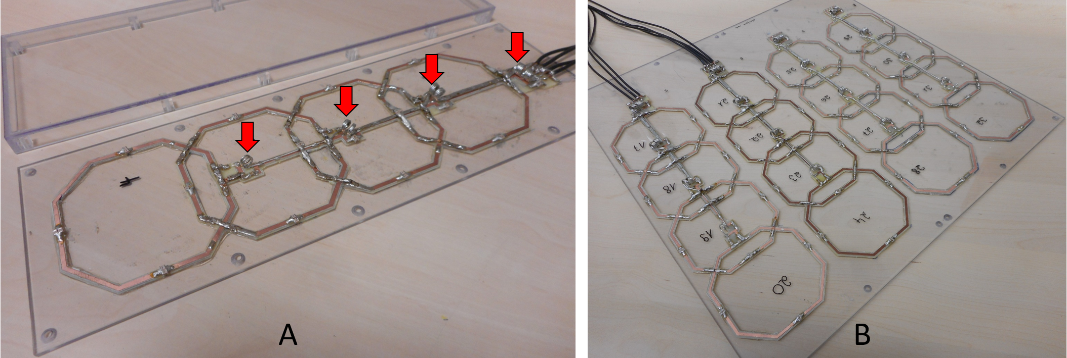
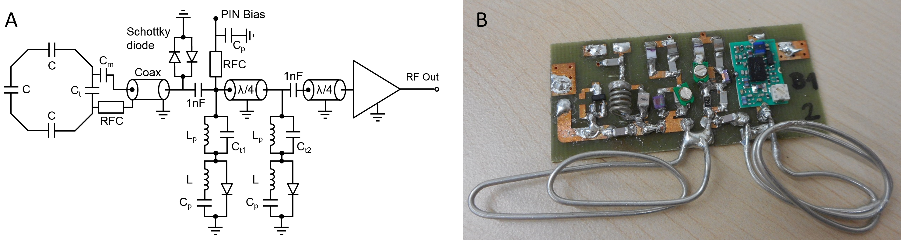
The presented coil is based on 10-cm loops (Figure 1A) which are milled (Protomat H60 milling machine, LPKF Laser & Electronics AG, Garbsen, Germany) from 1 mm FR4 substrate with 35 µm copper cladding. The loops have chamfered edges and are oriented along the z-direction. Next neighbors in the z-direction are decoupled by overlapping the elements2 while no additional decoupling networks are used for the other elements. Feeding is enabled using semi-rigid cables that are wound to form an inductance for a cable trap in front of the tuning/matching network of each loop (Figure 1A). In order to minimize coupling between the semi-rigid cable and the loops, the cable is centrally located with respect to the loops and soldered to the other semi-rigid cables of the other loops (Figure 1A). Cable traps are located every 10 cm along the z-direction to prevent coupling to RF during transmit. Four loops are combined in the z-direction to form a building block. On top of the subject, 4 building blocks, each positioned in a rectangular box (length in z/width in x/thickness in y direction of 396/127/18 mm), are combined to form a semi-flexible belt. Below the subject a rectangular box (450/450/20 mm) houses the other 4 building blocks on a plane (Figure 1B). Altogether, the space consumption is small when compared to previously published transceiver coils3,4. Low input impedance preamplifiers (WanTcom Inc., MN, USA) are mounted on a 1 mm FR4 board (58/26/1 mm). Two PIN diodes to ground (Figure 2A) connected by lambda-over-four semi-rigid cables (Figure 2B) protect the preamp during transmission. Furthermore, the detuning of the coil can be achieved by transforming the short provided by the PIN diodes to an open at the coil element’s tuning/matching circuit via the coaxial cable. This cable length then also enables preamplifier decoupling during receive. To protect the subject, a Schottky diode is also mounted on the board in parallel to one of the PIN diodes in case of PIN diode current failure. Preamplifier decoupling and detuning efficiency were measured on the bench while SNR gain and g-factors were assessed in MR measurements.Results and Discussion
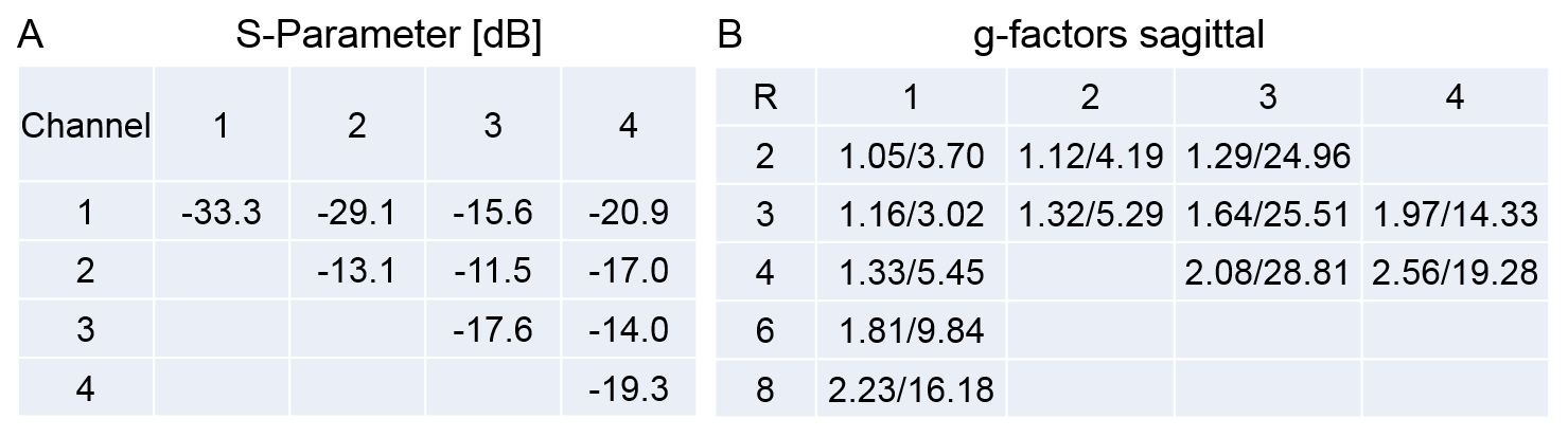
Measurements on the bench were performed using a 2-channel network analyzer (Agilent E5061A, Santa Clara, CA, USA). Figure 3A depicts the S-parameter matrix for the 4-channel building block. On average a reflection of Sxx = ‑18.0 ± 5.7 dB (worst case ‑13.1 dB) and a coupling of Sxy = ‑20.8 ± 5.7 dB (worst case ‑14 dB) could be achieved. Furthermore, g-factors in sagittal orientation are provided (Figure 3B). Detuning and preamplifier decoupling were measured with two loosely coupled loop probes, with the coil loop being power matched (50 Ohm) on the one hand and connected to the preamplifier board on the other hand. A value of -16.6 ± 1.7 dB for preamplifier decoupling and -18.5 ± 1.3 dB for detuning could be achieved. Further measurements were accomplished on a Siemens 7T whole‐body system (Magnetom 7T, Siemens Healthineers, Erlangen, Germany) using an oval body-sized phantom filled with agar (Figure 4A) and the 4-channel building block on top. SNR gain was calculated by dividing SNR maps acquired with the 4-channel building block by SNR maps acquired with the 32-channel Tx/Rx remote body coil1. In transversal (Figure 4B), sagittal (Figure 4C), and coronal (Figure 4D) orientation, robust SNR gain can be appreciated. Nevertheless, this comparison is biased since several channels of the 32-channel Tx/Rx remote body coil were not working properly at the time of measurement.Conclusion
While first results regarding additional SNR provided by only one building block of the 32-channel Rx-only coil look promising, further evaluation has to be performed with the entire 32-channel Rx coil assembly. With a full implementation of a 32-channel Rx-only coil, a setup comparable to the hardware configuration used in clinical settings at lower field strength can be provided at 7T. Furthermore, the smaller size of the 32-channel Rx coil will allow the investigation of larger patients compared to what is currently possible with local transceiver coils at 7T.Acknowledgements
The research leading to these results has received funding from the European Research Council under the European Union's Seventh Framework Programme (FP/2007-2013) / ERC Grant Agreement n. 291903 MRexcite.References
1. Orzada et al. A 32-channel integrated body coil for 7 Tesla whole-body imaging. Proc. Intl. Soc. MRM 24, #167 (2016)
2. Roemer PB, Edelstein WA, Hayes CE, Souza SP, Mueller OM. The NMR Phased Array. MRM 16, 192-225 (1990)
3. Orzada et al. A flexible 8-channel transmit/receive body coil for 7 T human imaging. Proc. Intl. Soc. MRM 15, #2999 (2009)
4. Rietsch et al. An 8Tx/32Rx RF Coil for 7T UHF Body MRI. Proc. Intl. Soc. MRM 24, #2131 (2016)
Figures