4324
A General Approach to Interfacing Multi-Nuclear RF Coils1NYU School of Medicine, Newyork, NY, United States
Synopsis
RF coils for multi-nuclear imaging require scanner-specific front-end interfaces that can limit their compatibility to one particular scanner platform. On the other hand, an intermediate interface that allows legacy coil compatibility with modern scanner architecture can be valuable in large institutions that operate a variety of scanners. In this work we describe the tools to build an intermediate interface with electronically controlled low-loss RF and DC signal pathways to provide a flexible means to route signals between the coil and scanner. While the tools are generally applicable to a variety of platforms, we focus on enabling compatibility between legacy multinuclear coils and a current scanner platform.
Purpose
Multi-nuclear RF coils are usually transmit-receive
devices having scanner-specific interfaces. An intermediate
interface allowing compatibility with different scanner
architectures can be valuable at institutions operating multiple scanners. Here
we present a framework for general intermediate interfaces for operating a
variety of possible coil/scanner combinations and describe a specific implementation
facilitating operation of multiple multi-nuclear coils on an upgraded scanner.
Methods
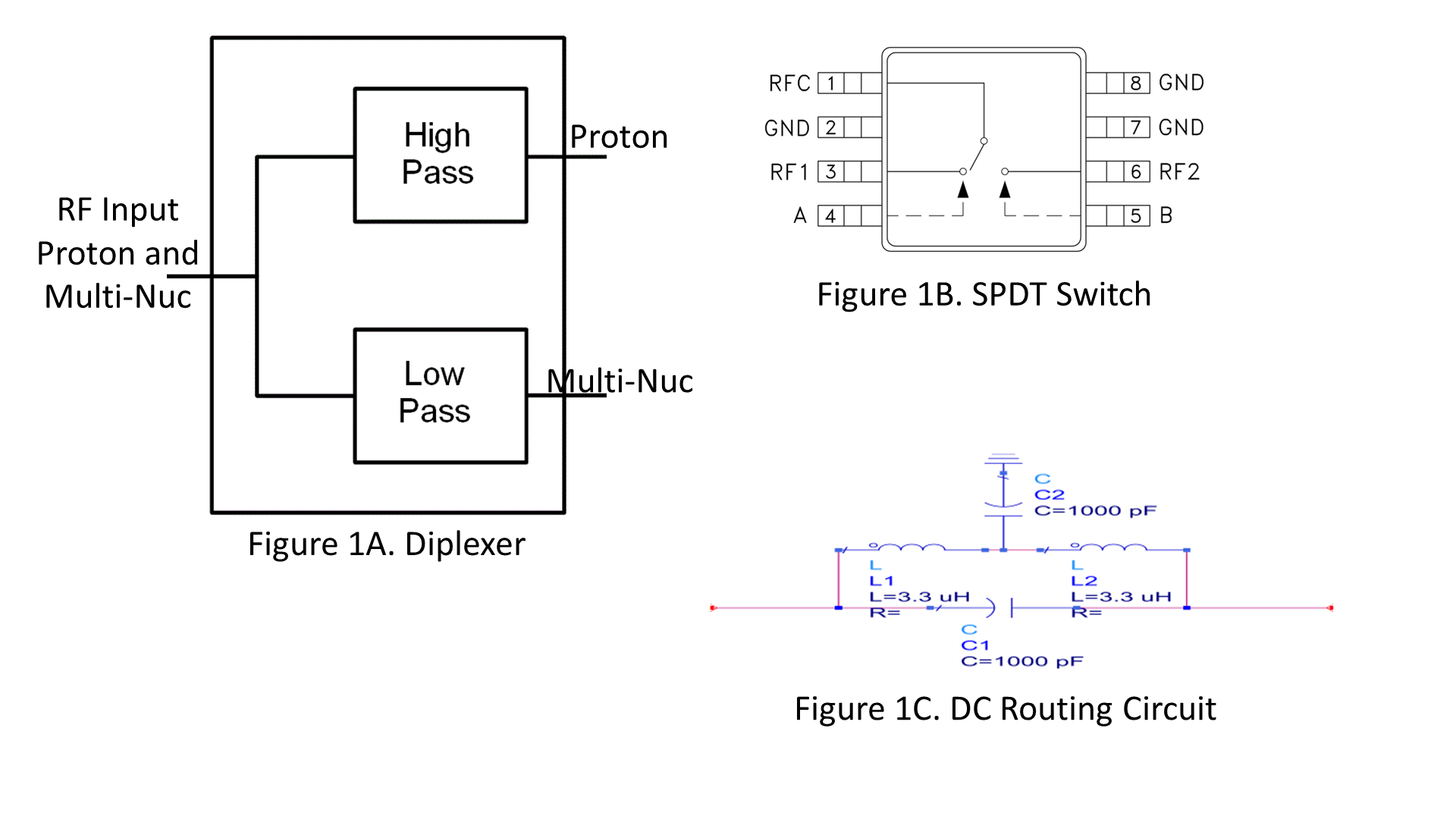
An intermediate interface needs to enable 1) RF transmission: If the scanner supports one transmit port and the RF coil has multiple connectors, a multiplexer circuit can separate the proton and X-nuclear signals. A diplexer circuitry is an efficient solution to achieve frequency multiplexing. The diplexer consists of a high-pass arm for proton operation and a low-pass arm to support X-nuclear operation (Fig.1A). Otherwise, if the scanner supports distinct proton and X-nuclear transmit ports and RF coil has a single connector, the diplexer circuit can be used to combine proton and X-nuclear signals and route them to the coil connector. With strategically choice of the low-pass filter leg cut-off frequency, the diplexer can transmit a wide range of X-nuclear signals. 2) RF reception: If the MR scanner requires distinct proton and X-nuclear receive ports and the RF coil has one connector, multiplexing is required to route the signals to appropriate ports. The same is true if the coil has multiple connectors and the scanner has distinct receive ports. Electronically-controlled single pole double throw (SPDT) switches (Fig.1B) provide an efficient solution to re-route receive signals to the appropriate ports. 3) Routing DC signals from the MR scanner to the coil to achieve proper de-tuning during RF transmission and reception, ensuring patient safety and proper coil performance. A three-port bias tee (Fig.1C) can be used to combine and transmit RF and DC signals.Specific Interface Box Implementation
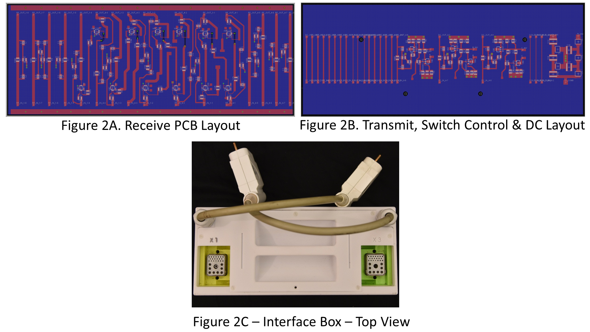
We recently upgraded from a Trio (Siemens) to a Prisma (Siemens) platform, which includes RF architecture incompatible with our multi-nuclear coils1,2,3. With the components and configurations described above, we designed an intermediate interface for operation of multiple legacy multi-nuclear coils on the Prisma platform. The specific design included 1) Two transmit cables and a diplexer circuit to combine separate proton and X-nuclear signals from the scanner and route them to the coil transmit plug. 2) Two sets of six non-magnetic broadband (10MHz-1GHz) SPDT switches routing the proton and X-nuclear receive signals from a single coil port for each of up to 12 coil elements to the corresponding, but separate proton and X-nuclear scanner ports. The switch control logic was generated by a network of MOSFET inverters, which were controlled by three PIN bias lines derived from the scanner. Coil files were modified to provide the appropriate bias, while no hardware modifications were required to the coils themselves. Design included minimizing the number of bias lines consumed by the SPDT switch logic for coil detuning, transmit/receive switch control. 3) DC routing circuits to pass bias from the scanner to the coil for the aforementioned functions. Interface circuitry was designed with Eagle software (CadSoft) (Fig 2A,2B) and housed in a 3-D printed enclosure (Fortus 360mc, Stratasys) fitting conveniently into the patient table (Fig 2C). Insertion loss was characterized on the bench, and practical performance was assessed through GRE images acquired on a Prisma system using several legacy multi-nuclear coils including a sodium proton body array (Stark Contrast) and a house-built sodium proton unilateral breast array4.Results
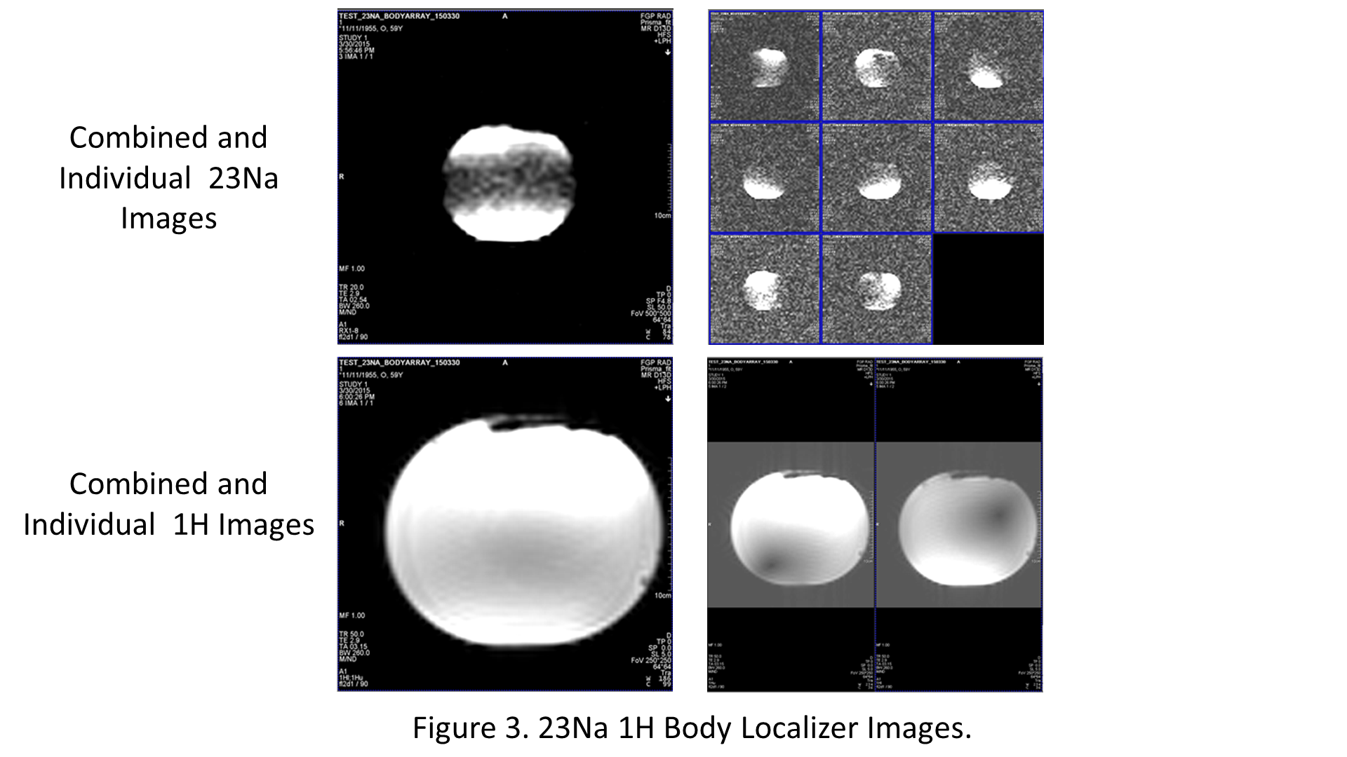
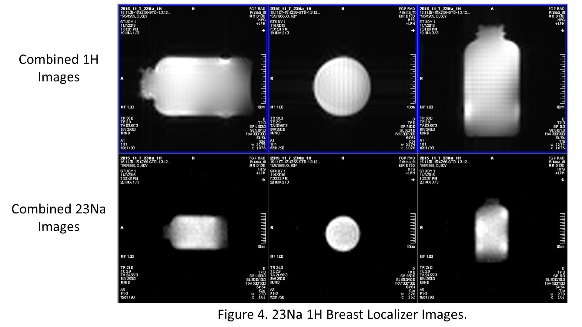
The insertion loss introduced by the diplexer circuitry and additional cabling and connectors was 0.5dB in the proton transmit path and less than 0.3dB at phosphorus and sodium frequencies. Reflection in the proton, sodium, and phosphorous transmit paths were all less than -15dB. The SPDT receive switches and cabling added approximately 0.6dB insertion loss to received signals, having negligible effect on SNR because it occurred after amplification. Proton and sodium GRE images (Fig.3,4) indicate that the interface enabled legacy coils to be utilized on the current scanner platform by properly routing transmit, receive and PIN bias signals to the multi-nuclear coils.Discussion and Conclusions
We describe a general framework for interfacing multinuclear RF coils to clinical scanners and constructed a specific interface enabling successful operation of legacy multi-nuclear coils on a new system. The interface provides compatibility without arduous hardware modifications to individual coils. At our center, the interface enabled the operation of six different phosphorous or sodium multi-nuclear multi-channel arrays. While our interface was customized for our case, the same principles could be applied to support other coil/platform combinations.Acknowledgements
No acknowledgement found.References
1. Makis .P. -https://www.ncbi.nlm.nih.gov/pubmed/24910264
2. Madeline.G -https://www.ncbi.nlm.nih.gov/pubmed/25751272
3. Inglese. M - https://www.ncbi.nlm.nih.gov/pubmed/20110245
4. Madelin G. - Proceedings ISMRM. Pp4634 2015.
Figures