4323
Half-wave Cavity Resonator for MR Coils Cable Assembly Testing1GE Healthcare Coils, Aurora, OH, United States
Synopsis
In MR coils or MR table there are multiple cables. Their presence is not desirable because they distort the B1 field; therefore multiple RF traps are distributed along the cable length to minimize induced cable currents. Tuning and performance of the MR cable traps’, also called cable baluns, on the cable are always difficult to predict, because the cable shape and position may vary. A coaxial half-wave cavity resonator is shown to be a precise tool to test cable balun assembly. It facilitates precise measurement of a balun’s coupling to the cable, its loss, and coupling to neighboring baluns.
Purpose
One of the requirements of an MRI coil is the image transparency of its on-coil RF electronics. To achieve this, engineers add considerable number of baluns in order to block the induced RF currents. Some of the highest currents are induced into the coils’ cables during TX phase. Bazooka RF traps are usually utilized for generating high impedance nodes on the cable. Each trap is tuned for the system frequency and placed in specific locations on the cable. With a traditional fixture, it is difficult to analyze/measure the ensemble of the cable and baluns. We propose to utilize a coaxial half wave cavity resonator for testing the entire cable with multiple traps.Theory
A coaxial half-wave resonator is comprised of a central conductor (cylindrical rod or cable) and concentric circular conductive shield or cavity. The resonant central conductor is cut to the half wavelength. In this application, we utilize the first halfwave resonant mode, or optionally a quarterwave mode.
A resonator could be described by a series resistance $$$R_0$$$, inductance $$$L_0$$$ and capacitance $$$C_0$$$, which leads to other characteristics as resonant frequency $$$f_0=1/(2 \pi \sqrt{L_0 C_0})$$$ and quality factor $$$Q_0=2 \pi f_0L_0/R_0$$$ [1]. A resonator’s series impedance is equal to $$Z_0(f)=R_0 \left( 1+j \frac{f}{f_0} Q_0 \left( 1-\frac{f_0^2}{f^2}\right)\right).\hspace{70pt} (1)$$
To assess the resonator’s characteristics, we utilize scattering parameters and the S21 transmission measurement. Two electric or magnetic probes provide (electric monopoles (Figures 1 and 3) or magnetic dipoles (loops)) ports into the cavity resonator. The S21 transmission is found to be inversely proportional to the impedance (1) $$$S_{21}(f)\propto Z_0^{-1}(f)$$$. When the S21 is expressed in dB, the proportionally becomes an addition with a slight linear frequency dependency with the intercept $$$k_0$$$ and slope $$$k_1$$$
$$S_{21,\text{dB}}(f)=k_0+k_1 f-20 \lg \Bigl\lvert 1+j \frac{f}{f_0} Q_0 \left( 1-\frac{f_0^2}{f^2}\right)\Bigr\rvert.\hspace{70pt} (2)$$
In order to describe the balun’s coupling to the cable, we consider a balun series model with a resistance $$$R_1$$$ , self-inductance $$$L_1$$$, and capacitance $$$C_1$$$, interacting with the cable modeled as a mutual inductance, $$$M_1$$$. We may define some derivations as balun’s resonant frequency $$$f_1=1/(2 \pi \sqrt{L_1 C_1})$$$, quality factor $$$Q_1=2 \pi f_1L_1/R_1$$$ , and magnetic coupling coefficient between the balun and the cable $$$ k_{M_{1}} = M_1/ \sqrt{L_0 L_1}$$$ . Utilizing method [2] the cable impedance is modified by the addition of the balun, therefore following equation (2), the observed S21 transmission of the cable with a balun
$$\tilde{S}_{21,\text{dB}}(f)=k_0+k_1 f-20 \lg \Bigl\lvert 1+j \frac{f}{f_0} Q_0 \left( 1-\frac{f_0^2}{f^2}\right)+\frac{\frac{f^2}{f_0 f_1} k_{M_{1}}^2 Q_0 Q_1}{1+j \frac{f}{f_1} Q_1 \left( 1-\frac{f_1^2}{f^2}\right)}\Bigr\rvert.\hspace{70pt} (3)$$
Equation (3) can be generalized for multiple baluns in various positions on the cable.
Apparatus
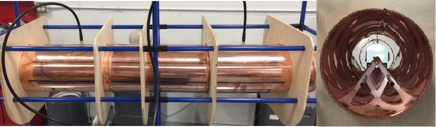
A 150 cm long and 30 cm diameter copper cylinder was assembled (Figure 1). It has two radially mounted electric monopole probe ports are placed internal to the cylinder, each in line with the other along the cylinder’s axial dimension, and spaced equidistant from the middle of the resonator. The resonator’s operational frequency of 127.73 MHz, is prescribed with a 117 cm copper rod is centered in the cylindrical cavity. Supports for the central rod are comprised of “W” shape dielectric supports. An additional high-power central magnetic excitation loop is provided for high power stress testing. In addition to the monopoles, there is an array of magnetic field loops distributed along the tube length (10 cm apart).These loops are utilized to monitor magnetic field intensity along the tube’s length.Results
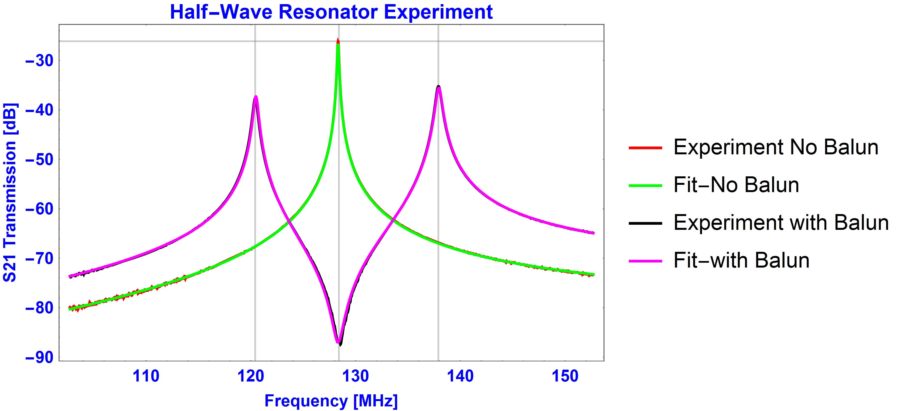
In order to confirm the tuning of the resonator, we need to test an empty cable (Figure 2). The numerical data were fitted utilizing the equation (2). As can be observed from the fitted data, the analytical curves are nearly indistinguishable from the experimental measurements. Adding a balun to the tuned central conductor, the prior S21 response’s middle peak now splits forming two peaks off resonance. The coupling coefficients may be resolved utilizing measurements of the separation between the low and high frequency peaks. The measurement of the relative magnitude of the left and right peaks vs the original empty resonator peak resolves the series resistance of the balun.Conclusions
A half-wave coaxial cavity resonator may replace the existing fixtures for testing cable. It allows testing the entire cable assembly. Further, connecting a power source to the high power port facilitates RF stress testing – heating. The array of the pickup loops one can observe B1 distortion properties along the cable.Acknowledgements
No acknowledgement found.References
1. D.M. Pozar. Microwave Engineering 3rd Edition, ch. 6.
2. L.D. Landau, L.P Pitaevskii, E.M. Lifshits, Electrodynamics of Continuous Media, 2nd Edition: Volume 8, § 62
Figures