4320
A bent dipole antenna and 4-channel loop array for 1H/31P brain application at 3 T MRI1Institute of Neuroscience and Medicine - 4 Medical Imaging Physics Forschungszentrum Juelich GmbH, Juelich, Germany, 2Current Address: Medical Physics in Radiology, German Cancer Research Centre (DKFZ), Heidelberg, Germany, 3Department of Neurology, Faculty of Medicine, RWTH Aachen University, JARA, Aachen, Germany
Synopsis
A dipole antenna achieves good isolation from a loop coil when it is located over the centre of a loop coil. Such an arrangement can be used as a dual-tuned coil, by tuning the dipole and the loop to the 1H and X frequencies, respectively. At 3 T, however, the length of a dipole antenna is too long to be of use for brain applications. In this study, we bent the dipole antenna around the head to overcome the length problem. We then evaluated the feasibility of combining two dipole antennae and a 4-loop array for 1H/31P application.
Purpose
Decoupling between 1H and X-nuclei elements is essential in a dual-tuned coil system. The geometries of 1H elements can be optimized to generate magnetic fields orthogonal to those of X-nuclei elements for decoupling 1–3. A dipole antenna can achieve good isolation from a loop when it is located over the centre of the loop coil since it generates a magnetic field vector orthogonal to direction of the loop coil. Moreover, the dipole antenna has been shown to achieve great isolation (-40 dB) when integrated with a 23Na array at 9.4 T 4. However, the dipole antenna is too long (117 cm) to use this advantage for brain MRI/S at 3 T. In this study, we modified the shape of dipole antenna by bending it around the head to overcome the length problem. We evaluated the isolation between the dipole (1H) and loop coils (31P) and B1+ field distribution for 1H/31P brain MRI/S at 3 T.
Methods
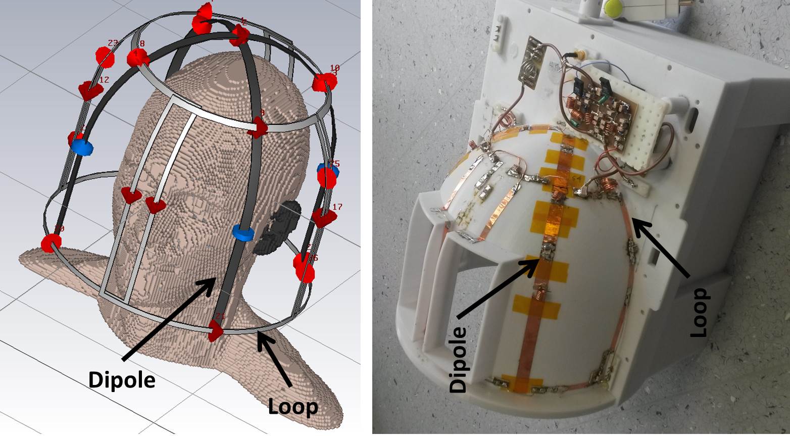
Figure 1 shows the probe configuration. It consists of two bent dipoles (1H) and a 4-loop array (31P). The dipoles are 60 cm long and have a resonance frequency of 200 MHz, which was reduced to 123 MHz using 4 inductors, located 10 cm and 20 cm from the feed point. The dipoles were arranged orthogonally and driven in quadrature. Four loop coils were located such that the dipoles pass over the centre of the loops. The array was driven in quadrature using a Wilkinson divider and a pair of 90° hybrids. Loops were decoupled from one another by overlapping and capacitive decoupling 5.
To evaluate the B1+ field distribution and coil sensitivity, we conducted FDTD simulations (Microwave Studio, CST) and made phantom measurements. For 1H/31P signal measurement, we used a 2 litre water phantom containing 2 g KH2PO4, 1.25 g NiSO4 x 6H2O and 5 g NaCl. Performance of the quadrature bent dipole probe was compared to a commercial birdcage coil (TX/RX HEAD, Siemens). Because the flip angle value can be varied by calibration, we calculated sensitivity for quantitative comparison. The SNR of proton density weighted gradient echo images is a function of flip angle, proton density, and sensitivity. Therefore the sensitivity was calculated by dividing SNR by flip angle distribution. The flip angle distribution was acquired using AFI 6. For 31P, we acquired an FID signal with ISIS VOI selection 7. To evaluate signal degradation of 31P due to the presence of the dipole antenna, we measured loaded and unloaded Q-factors of the 31P loop coil with and without the dipoles present.
Results
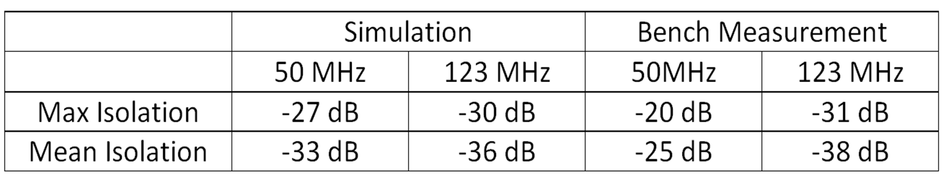
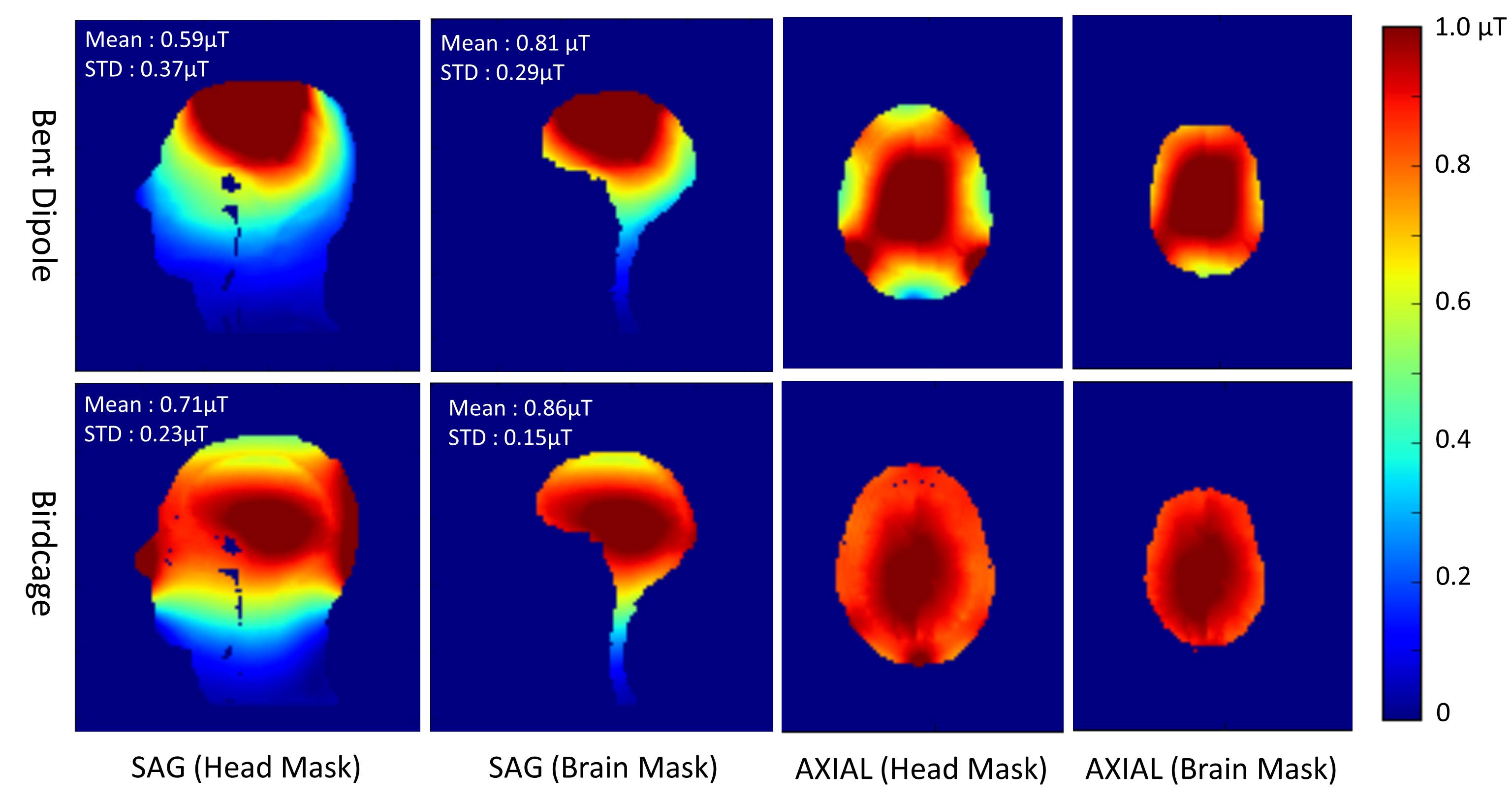
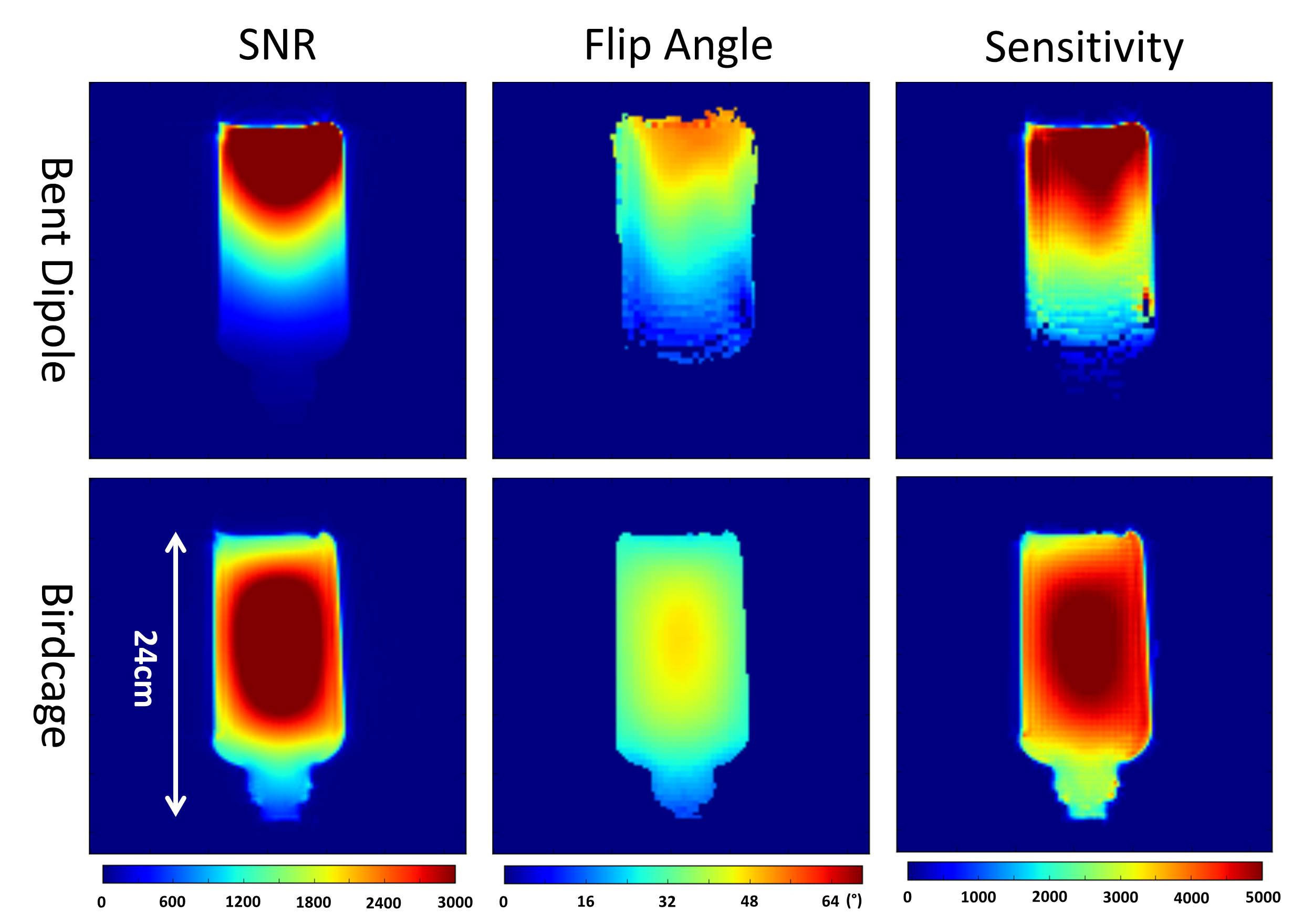
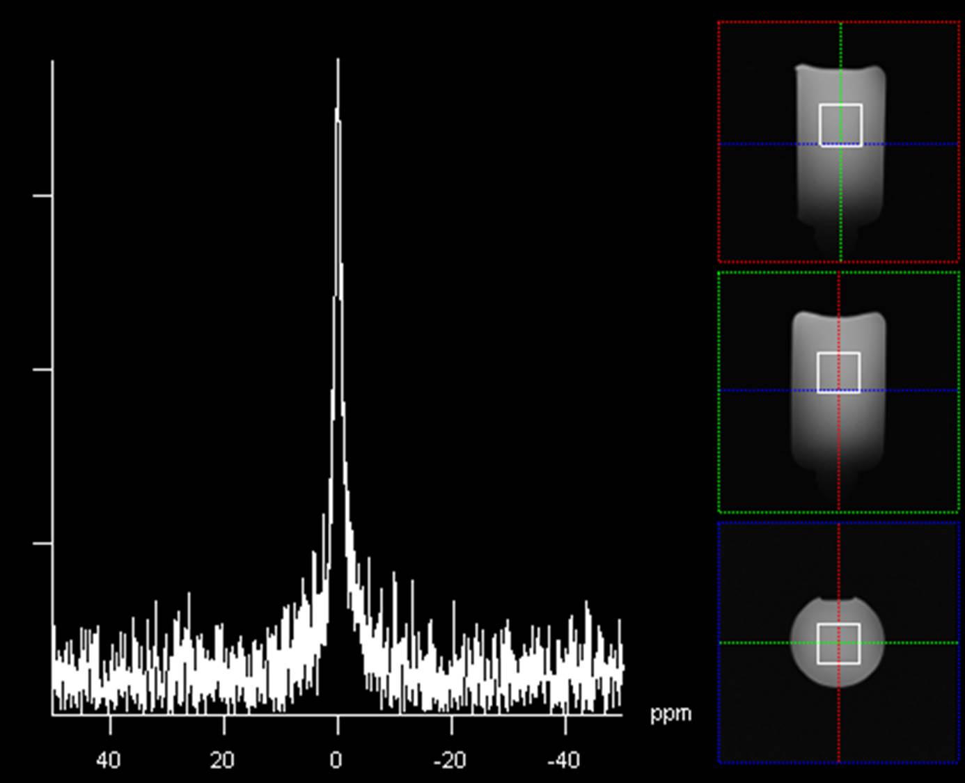
Table 1 shows measured isolation between dipole antenna (1H) and loop array (31P). The maximum isolation was -20 dB at 50 MHz and -31 dB at 123 MHz. Figure 2 shows simulated B1+ field distribution of the bent dipole antenna and the birdcage coil. The birdcage provided highest B1+ field strength at the centre of the brain, while the bent dipole antenna provided highest B1+ at the top of the head. Within the brain, the bent dipole antenna provided similar average B1+ efficiency but the field was focused on the top of the brain. Figure 3 shows the measured SNR, flip angle and sensitivity map of phantom. In agreement with the simulations, the birdcage coil provided highest flip angle and sensitivity at the centre of the coil, while the bent dipole antenna provided focused flip angle and sensitivity at the top of the phantom. Both coils provided a similar range of maximum sensitivity. Figure 4 shows a 31P spectrum acquired with the 4-loop array. The Q-factors (unloaded/loaded/ratio) of the loop coil were 227/125/1.8, without dipole antenna, and 195/117/1.7 with dipole antenna present.
Discussion and conclusion
Simulation results show that the dipole antenna provides similar B1+ field efficiency over the whole brain on average, while focused to the upper part of the brain. Although the dipole antenna provides focused field distribution and less uniformity, it provided sufficient isolation when integrated with the 4-loop 31P array. Phantom results further confirm that the dipole antenna provided similar maximum sensitivity to the single tuned birdcage, although it is focused on the top of the phantom. For 31P loop coils, the loaded/unloaded Q-ratio was decreased by less than 10 % when the dipole antenna was integrated. Because the dipole antenna provides similar maximum sensitivity to the single tuned coil and sufficient isolation from the X-nuclei coil, the quadrature bent dipole antenna and 4-loop array system is a promising alternative dual-tuned RF coil design.
Acknowledgements
No acknowledgement found.References
1. Bottomley PA, Hardy CJ, Roemer PB, Mueller OM. Proton-decoupled, overhauser-enhanced, spatially localized carbon-13 spectroscopy in humans. Magn. Reson. Med. 1989;12:348–363.
2. Augath M, Heiler P, Kirsch S, Schad LR. In vivo 39K, 23Na and 1H MR imaging using a triple resonant RF coil setup. J. Magn. Reson. 2009;200:134–136.
3. Yan X, Xue R, Zhang X. A monopole/loop dual-tuned RF coil for ultrahigh field MRI. Quant. Imaging Med. Surg. 2014;4:225–231.
4. Shajan G, Mirkes C, Buckenmaier K, et al. Three-layered radio frequency coil arrangement for sodium MRI of the human brain at 9.4 Tesla. Magn. Reson. Med. 2016;75:spcone-spcone.
5. von Morze C, Tropp J, Banerjee S, et al. An eight-channel, nonoverlapping phased array coil with capacitive decoupling for parallel MRI at 3 T. Concepts Magn. Reson. Part B Magn. Reson. Eng. 2007;31B:37–43.
6. Yarnykh VL. Actual flip-angle imaging in the pulsed steady state: a method for rapid three-dimensional mapping of the transmitted radiofrequency field. Magn. Reson. Med. 2007;57:192–200.
7. Ordidge RJ, Connelly A, Lohman JAB. Image-selected in Vivo spectroscopy (ISIS). A new technique for spatially selective nmr spectroscopy. J. Magn. Reson. 1969 1986;66:283–294.
Figures