Elizaveta Motovilova1, Yang Gao2,3, Zhihua Ren1, Xiaotong Zhang2,3, and Shao Ying Huang1,4
1Engineering Product Development, Singapore University of Technology and Design, Singapore, Singapore, 2Interdisciplinary Institute of Neuroscience and Technology, Zhejiang University, Hangzhou, People's Republic of China, 3College of Biomedical Engineering & Instrument Science, Zhejiang University, Hangzhou, People's Republic of China, 4Department of Surgery, National University of Singapore, Singapore, Singapore
Synopsis
This study presents a numerical evaluation
of a novel RF coil array for human head imaging at 7T. The 8-element coil was
developed using a metamaterial concept. As the main advantage of a metamaterial
transmission line is that the uniformity of RF-magnetic near field does not dependent
of the TL’s physical length, we applied this meta-TL concept to a loop in order
to achieve a larger coverage of B1+-field. Numerical comparison
to conventional designs demonstrate an improved B1-field homogeneity
of the proposed coil. Preliminary experimental studies show a reasonable
agreement with simulations.
Introduction
Metamaterial-inspired microstrip lines (MLs) have been recently suggested for improving B1-field penetration and homogeneity of radio-frequency (RF) coils for ultra-high field (UHF) MRI1-3. Several modifications of MLs according to the metamaterial-concept have demonstrated an improved B1-field penetration into the region of interests (ROI) with a uniform and high B1-field intensity2-3. The main advantage of metamaterial transmission lines (TLs) is that, in theory, the uniformity of the B1-field does not depend on the physical length of the TL, which provides an opportunity to make RF coils with sizes larger than the Larmor wavelength that is shortened due to an increased B0. This paper proposes a new approach in using the metamaterial TL concept in which the meta-TL is folded into a loop covering a large ROI.Theory
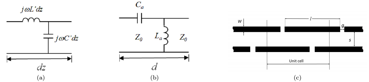
A conventional TL can be modeled using distributed circuit elements: impedance in series, $$$\small Z=j\omega L'dz=j\omega\mu dz$$$, and admittance in shunt, $$$\small Y=j\omega C' dz=j\omega\epsilon dz$$$,4 where $$$\small L'$$$ and $$$\small C'$$$ are the distributed inductance and capacitance (Fig.1(a)). When additional periodic series capacitor ($$$\small C_a$$$) and shunt inductor ($$$\small L_a$$$) are added (Fig.1(b)), additional permeability and permittivity are introduced to the line and the total equivalent electromagnetic properties become $$$\small\mu_e =\frac{Z}{j\omega}=\mu - \frac{1}{\omega^{2}C_a}$$$, $$$\small\epsilon_e=\frac{Y}{j\omega}=\epsilon - \frac{1}{\omega^{2}L_a}$$$. Since the wave behavior depends on the equivalent electromagnetic properties of the TL, it can be manipulated by tailoring the additional periodic elements. Ways to realize metamaterial concept on a ML for RF coil design was suggested, e.g. using surface mount components2 or shunt stubs and interdigital capacitors3. We have hereby extended the metamaterial concept application beyond ML and systematically studied a set of loop modifications that can benefit at UHF. Loop array was chosen due to a large $$$B_1$$$ coverage it can attain with a single element. For additional distributed elements we used gaps as serial $$$C_a$$$ and a coupled line as shunt $$$L_a$$$ (Fig.1(c)). We found that a coupled TL with periodic gaps can help to realize a loop with electrically large circumference, whereas efficient and homogeneous near-field RF-magnetic distribution.Methods
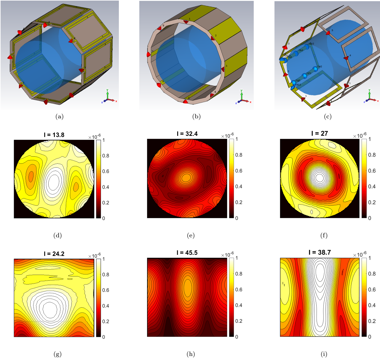
We present a novel design of an 8-element head coil for 7T human head imaging. The full-wave numerical simulation was conducted by using CST5. For comparison purpose, besides the proposed metamaterial coil, a conventional 8-element TEM coil6 and 8-element loop coil7 were also simulated, with similar inner diameters of 23.4cm, 23.4cm, and 24cm, respectively, as shown in Fig.1(a)-(c). A homogeneous cylindrical phantom was placed in the center of each of the three coils, which has the length of 26cm, and diameter of 12cm, with $$$\epsilon_{r}=$$$78 and $$$\sigma=$$$0.59S/m to resemble average human brain. All elements of each coil were tuned and matched using co-simulation at 297.2MHz, and all coils were driven in a circular-polarized (CP) mode with 45o incremental phase shift between adjacent channels.
An experiment was conducted on a Siemens MATNETOM 7T (Erlangen, Germany) scanner, with only one coil element of the proposed coil utilized for Tx/Rx. A quality control Siemens phantom (3.75g NiSO4·6H2O+5g NaCl per 1000g H2O dist.) with length 20cm and diameter 12cm was placed close to the surface of the coil.Results
Fig.1(d)-(f) and Fig.1(g)-(i) show calculated $$$B_1^+$$$-field on the central axial and coronal slices for the three coils, respectively. The $$$B_1^+$$$ inhomogeneity was quantified by using the formula $$$I=std(B_1^+)/\overline{B_1^+}$$$ and the corresponding number for each case is shown in Fig.2(d)-(i). The TEM and loop array coils both show a pronounced circular intensity peak in the center with an asymmetric dark ring around, whereas the proposed coil exhibits a more homogeneous $$$B_1^+$$$-field distribution (imhomogenetity equals 13.8 and 24.2 in axial and coronal slices respectively).
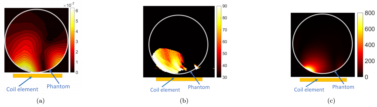
Preliminary experiments were conducted by using single-element coil of the proposed design. The corresponding $$$B_1^+$$$ was simulated to mimic the physical environment, while the actual flip angle (FA) map8 and an SNR map was measured on the central axial slice, all of which are shown in Fig.3(a)-(c). Due to only one coil element was utilized for signal reception, significant SNR drop was observed in regions far to the coil, thus in these regions the FA measurement was unreliable. Nevertheless, in the regions close to the coil, the simulated and measured B$$$_1^+$$$ share a very similar distribution pattern as well as an attenuation trend, indicating a reasonable agreement between the two results.Conclusion
A
novel RF-coil design has been proposed based on metamaterial theory. Comparison to conventional designs demonstrate an improved B1-field homogeneity of the proposed coil. A pilot experiment was conducted at 7T to evaluate the
new coil design, and a reasonable agreement has been found between simulated
and measured B1+-maps.Acknowledgements
This research was supported by SUTD President's Graduate Fellowship. I would like to take this opportunity to express my sincere gratitude for their support.References
1. Sohn, Sung-Min, et al. "RF Head coil design with improved RF magnetic near-fields uniformity for magnetic resonance imaging (MRI) systems." IEEE transactions on microwave theory and techniques 62.8 (2014): 1784-1789.
2. Panda, Vijayaraghavan, J. T. Vaughan, and Anand Gopinath. "7T MRI RF Head Coil with metamaterial elements." 2015 IEEE MTT-S International Microwave Symposium. IEEE, 2015.
3. Panda - Zeroth-Order Resonator with Stepped Impedance for 7T Magnetic Resonance RF Coil - Proceedings ISMRM 2016.
4. Pozar, David M. Microwave engineering. John Wiley & Sons, 2009.
5. CST Microwave Studio 2015 (Darmstadt, Germany), www.cst.com.
6. Yan, Xinqiang, et al. "Optimization of an 8-channel loop-array coil for a 7 T MRI system with the guidance of a co-simulation approach." Applied Magnetic Resonance 45.5 (2014): 437-449.
7. Akgun, Can E., et al. "Stepped impedance resonators for high-field magnetic resonance imaging." IEEE Transactions on Biomedical Engineering 61.2 (2014): 327-333
8. Yarnykh VL. Actual flip-angle imaging in the pulsed steady state: a method for rapid three-dimensional mapping of the transmitted radiofrequency field. Magn Reson Med 2007;57:192–200.