4317
Combining loops and dipoles at 7 T and 10.5 T: a simulation study1Division Imaging, Department of Radiology, University Medical Center Utrecht, Utrecht, Netherlands, 2Center for Magnetic Resonance Research, Department of Radiology, University of Minnesota, Minnesota, United States, 3Division Imaging, Department of Radiotherapy, University Medical Center Utrecht, Utrecht, Netherlands, 4Biomedical Image Analysis, Eindhoven University of Technology, Eindhoven, Netherlands
Synopsis
The combined use of loops and dipoles as transmit elements is investigated at 7 T and 10.5 T. A 8 channel loop/8 channel dipole setup is compared to a 16 channel dipole setup at both field strengths. It is found that combining loops and dipoles enhances transmit performance at both field strengths. The 8 loop/8 dipole transmit setup is the best performing setup at both field strengths. Additionally, increasing the channel count from 8 to 16 channels provides an almost 50% reduction in SAR10g/(B1+)2 at 10.5 T.
Purpose
Combining loops and dipoles was demonstrated to improve transmit and receive performance for body imaging at 7 Tesla1,2. A recent study demonstrated the potential of using fractionated dipole antennas for body imaging at 10.5 T (447 MHz)3. Combining loops and dipoles might be a next step in optimizing the 10.5 T transmit setup for body imaging. However, several studies demonstrate that dipoles outperform loops when moving to higher field strengths2,4. In this work, an explorative simulation study was done to investigate the performance of combined loop dipole elements at 10.5 T and 7 T. A 8 channel loop/8 channel dipole array was compared to a 16 channel dipole array at both field strengths.Methods
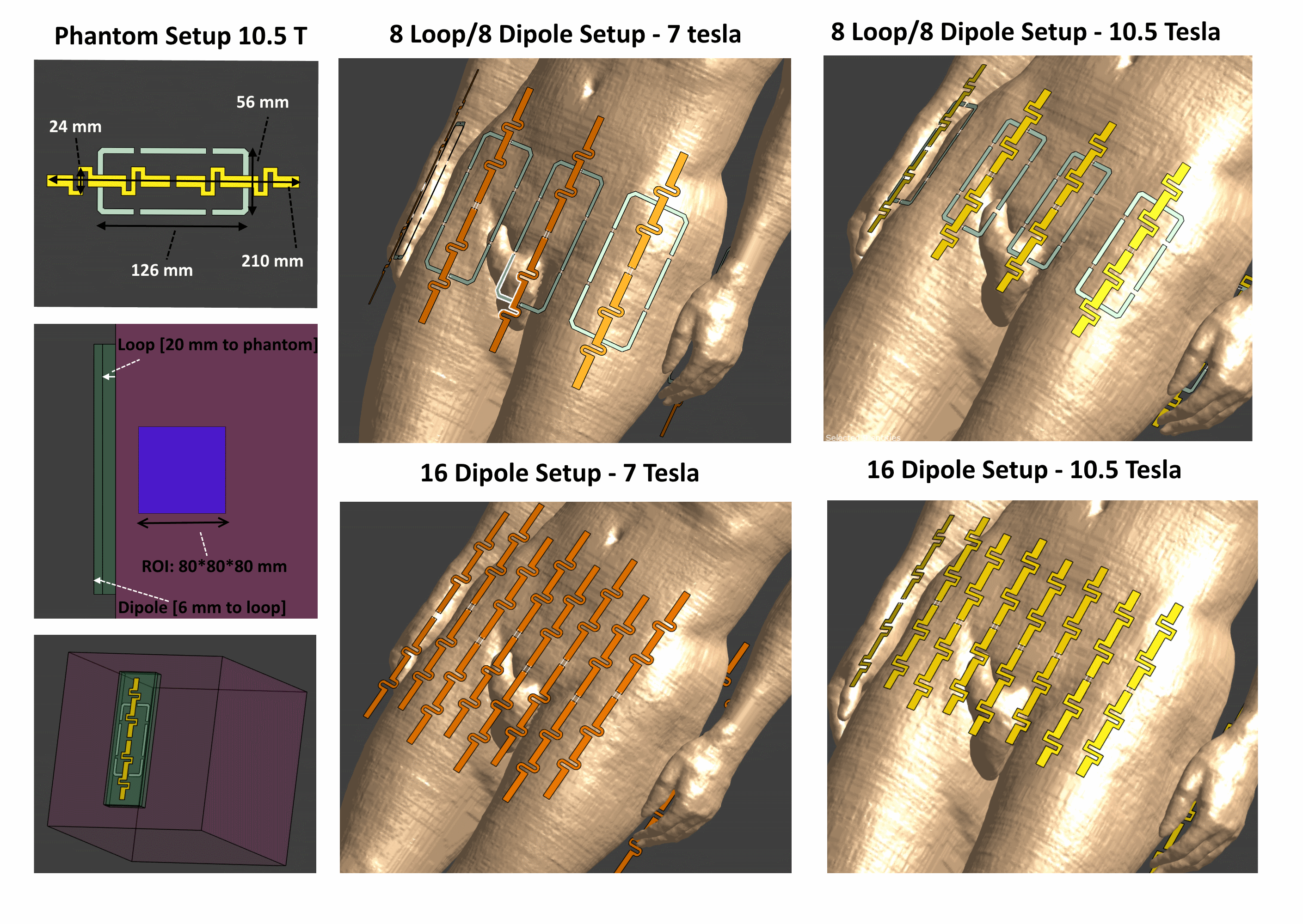
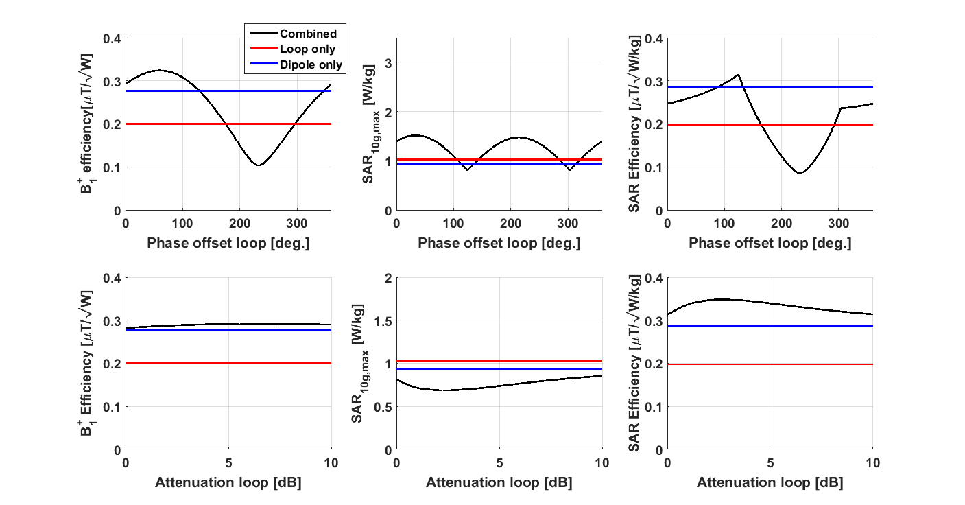
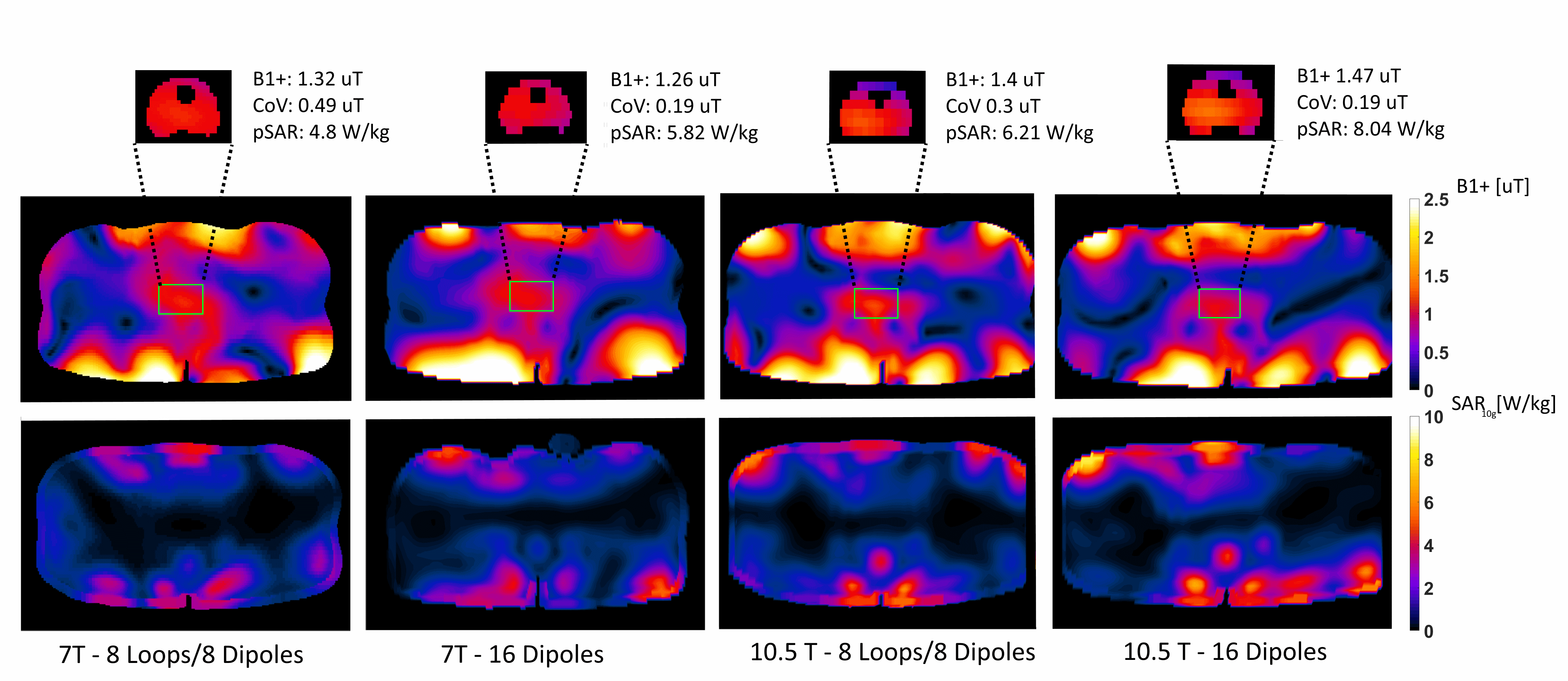
Finite difference time-domain simulations (Sim4Life, Zurich Med Tech, Zurich) were carried out for a two channel loop-dipole element on a cubical phantom (figure 1) to determine if and how the two elements needed to be combined at 447 MHz. The loop was tuned to 447 MHz using six capacitors of 2.6 pF. The dipole and loop are inherently decoupled (S12 = -38.2 dB). The simulation results for both separate channels were combined in postprocessing, while cycling through the phase offset and attenuation of the loop driving amplitude. A similar simulation study was already carried out at 298 MHz1. Two transmit setups (16 dipoles and 8 loops/8 dipoles) were simulated on human model Duke for both 298 and 447 MHz (figure 1)5. The loops were tuned to 298 and 447 MHz by respectively using six 3.7 and 2.6 pF capacitors. Simulation results were normalized to available power, 10g averaged Q-matrices were determined for all simulation setups. Virtual observation points were determined, resulting in an SAR overestimation of 5%6. The complex input vectors were optimized to maximize the B1+/√SARmax in the prostate.Results
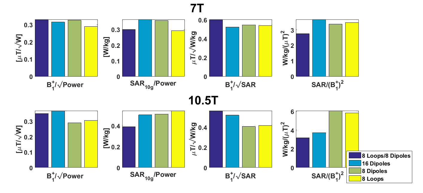
Figure 2 shows the results for a two channel setup on a phantom. Combining a loop and a dipole can lead to an increase in transmit-efficiency (B1+/√W), while simultaneously increasing the SAR efficiency (B1+/√SAR, +20% in the ROI). The dipole outperformed the loop in terms of transmit- and SAR-efficiency. Figures 3 and 4 show the result of the simulations on the human model Duke. The results at 7 T indicate that moving from 8 to 16 dipoles does not increase SAR efficiency. However, combining 8 loops and 8 dipoles increases SAR efficiency by 11%. The 8 dipoles slightly outperform the 8 loops at 7 T. At 10.5 T, the 8 loop/8 dipole array outperforms the 16 dipole array. Both setups clearly outperform the 8 dipole setup, SAR efficiency increases more than 25%. The 8 loops and 8 dipoles perform very comparable at 10.5 T, with the loops having a slightly higher SAR efficiency.Discussion
Figure 2 shows that combining a single loop and dipole provides a small increase in SAR efficiency at 10.5T, comparable results have been demonstrated at 7 T1. Figures 3 and 4 indicate that by increasing the channel count at 7 T, the transmit and SAR efficiency increases when combining loops and dipoles (as already demonstrated1), but not when increasing the number of dipoles. At 10.5 T, the 8 loop/8 dipole setup yields the highest SAR efficiency. Increasing the channel count provides a decrease in the SAR/(B1+)2-ratio to almost 50% , which enables to significantly relieve SAR constraints. The benefits of increasing channel count are stronger at 10.5 T than at 7 T. Figures 3 and 4 also show that peak SAR is higher for all setups at 10.5 T. It is hypothesized that by increasing channel count, SAR can be distributed more evenly, this effect can be more pronounced at 10.5 T. Figure 4 shows that the 8 dipoles outperform the 8 loops at 7 T but not at 10.5 T, which is unexpected, and might be caused by the loops being positioned closer to the body (6 mm), and by the dipoles being shielded by the loops. However, the differences are very small and both designs (loop and dipole) may not be optimal yet in terms of distance from the subject.Conclusion
For both 7 T and 10.5 T, a setup of 8 loops/8 dipoles provides better transmit performance than a 16 dipole setup. The results shown here clearly indicate that moving to 16 channels will be beneficial for transmit performance at 10.5 T. The relief in SAR constraints by almost 50% can be utilized to decrease scan-time. The optimum transmit setup for 10.5 T appears to be a combined loop/dipole setup.Acknowledgements
This work was funded by the Dutch Technology Foundation STW, grantnumber 13783References
1. Ertürk MA, Raaijmakers AJE, Adriany G, Ugurbil K, Metzger GJ. A 16-channel combined loop-dipole transceiver array for 7 Tesla body MRI. Magnetic Resonance in Medicine. 2016;doi:10.1002/mrm.26153.
2. Wiggins GC, Zhang B, Cloos M, Lattanzi R, Chen G, Lakshmanan K, Haemer G, Sodickson DK. Mixing loops and electric dipole antennas for increased sensitivity at 7 Tesla. In: Proc Int Soc Magn Reson Med. Vol. 21. 2013. p. 2737.
3. Ertürk MA, Wu X, Eryaman Y, Van de Moortele P-F, Auerbach EJ, Lagore RL, DelaBarre L, Vaughan JT, Ugurbil K, Adriany G, et al. Toward imaging the body at 10.5 tesla. Magnetic Resonance in Medicine. 2016;doi:10.1002/mrm.26487.
4. Raaijmakers AJE, Luijten PR, van den Berg CAT. Dipole antennas for ultrahigh-field body imaging: a comparison with loop coils. NMR in Biomedicine. 2016;29(9):1122–1130.
5. Kuster AC and WK and EGH and KH and MZ and EN and WR and RJ and WB and JC and BK and PS and H-PH and J. The Virtual Family—development of surface-based anatomical models of two adults and two children for dosimetric simulations. Physics in Medicine and Biology. 2010;55(2):N23.
6. Eichfelder G, Gebhardt M. Local specific absorption rate control for parallel transmission by virtual observation points. Magnetic Resonance in Medicine. 2011;66(5):1468–1476.
Figures