4316
Utilization of Slotted Antennas for Capturing Ideal Current Patterns at Ultra High FieldLeeor Alon1,2, Christopher M. Collins1,2, Daniel K. Sodickson1,2, and Riccardo Lattanzi1,2
1Center for Advanced Imaging Innovation and Research (CAI2R), New York University School of Medicine, New York, NY, United States, 2Center for Biomedical Imaging, New York University School of Medicine, New York, NY, United States
Synopsis
Slotted antennas were demonstrated to be highly efficient coils for ultra high field magnetic resonance imaging. In this work, we elucidate the performance of such antennas using the ideal current patterns theoretical work.
Purpose
Recent work has shown that tradition coil design are not optimal at ultra-high field (UHF, >=7T) [1,2]. Studies on ideal current patterns (ICP) at UHF have shown that the ultimate intrinsic signal-to-noise (SNR) at the center of a cylindrical dielectric sample can be achieved using distributed z-oriented current patterns rotating at the Larmor frequency [1]. This configuration cannot be achieved with typical conductive strips [3], which limit the current patterns to the conductor’s surfaces, therefore, limiting the optimal SNR at the center, and by reciprocity, transmit efficiency. Last year, a slot antenna concept for UHF was introduced, demonstrating an antenna structure for wide field-of-view imaging using a single antenna element [4]. In this work, we compared performance of a single planar slot antenna with a 3-dipole array. We also juxtaposed the electric field vectors produced by these coil structures to ideal current patterns, which at UHF correspond to the projection of the electric field on a spin precessing at the voxel of interest [2].Methods
Simulations were performed using the Comsol Multiphysics 5.2a finite element modeling (FEM) solver (Burlington, MA, USA). A 0.8cm x 0.4cm x 0.8cm rectangular phantom with relative permittivity of 45.33 and conductivity of 0.33 S/m, resembling average electrical tissue properties of the torso at 300 MHz was used in the simulations. Two simulation were performed: the first, with a three dipole array positioned 3 cm above the phantom. The distance between the dipoles in the x-direction was 20cm. Each dipole was 50 cm long and 1cm in diameter with a match <9.9 dB. In the second simulation, a single slot antenna modeled positioned 3 cm above the phantom. For the slot antenna, a conductor of length 46.3cm x 25cm was modeled with a 1cm by 43.8cm gap in the middle. Antennas were driven with a 1V source at the central port operating at 300 MHz. Transmit fields (B1+) of both simulations normalized by the square root of total power deposition inside the phantom was plotted, central B1+ was evaluated, and electric field vectors 1cm above the phantom were plotted (coronal). Similarly, ICP were computed for optimal SNR at the center of a cylinder with radius of 20cm and length of 80cm. ICP were defined on a cylindrical surface of radius=20.5cm, while the system shield was modeled at radius=34.25cm. The conductivity and relative permittivity of the cylindrical phantom were 0.33 S/m and 45.33, respectively. Simulations for an array with 8-dipoles and one with 4-slots were performed with the same cylindrical phantom, where transmit efficiency was evaluated.Results
B1+ efficiency of a planar slot and a three-dipole antenna setup are shown in figure 1. The B1+ at the center of the dipole and slot setups were 6.38e-8 Tesla and 1.09e-7 Tesla, respectively. This corresponds to a central B1+ efficiency improvement > 70% for the single slot setup. Power deposition for the dipole and slot setups was 141.3 and 395.3 Watts, respectively. Figure 2A shows that the ICP are dominated by distributed z-directed currents, contributing the optimal performance at the center. The electric field distribution for the dipoles and slot antennas are shown in figure 2B and C, respectively, demonstrating distributed z-directed vectors in the slot antenna simulations. Figure 3 illustrates transmit efficiency comparing a 4-slot antenna and 8-channel dipole arrays. The improvement is observed in transmit efficiency at the phantom center alongside a reduction in homogeneity.Conclusions
As observed by the ICP simulation, distributed z-directed electric field vectors are responsible for optimizing transmit efficiency at the center of the cylinder. Distributed z-directed electric field vectors were observed when utilizing slot antennas and can explain improved efficiency over dipoles.Acknowledgements
Funding from NIH through R01 EB011551, R01 EB002568, and P41 EB017183.References
[1] Lattanzi R, Sodickson DK. Mag. Reson. Med. 2012; 68:286–304. [2] Sodickson DK, et al. Intl. Soc. Mag. Reson. Med. 24 (2016). p. 389. [3] Raaijmakers AJ. Magn. Reson. Med. 2011 Nov;66(5):1488-97. [4]. Alon et al. Proc. Intl. Soc. Mag. Reson. Med. 24 (2016). P. 3516.Figures
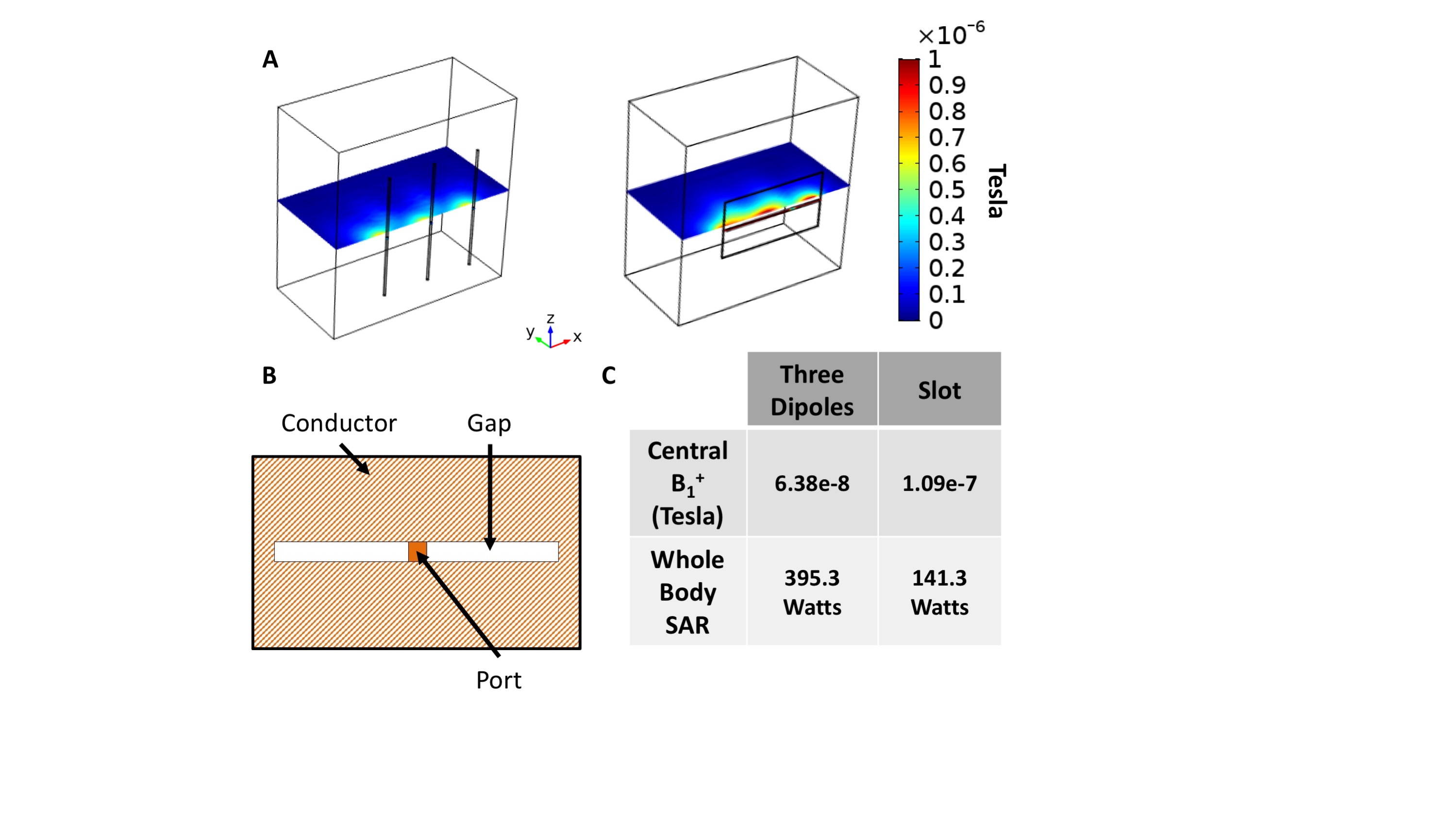
Comparison of the transmit performance of a 3-dipole array (A, left) and
a single slot antenna (A, right). Illustration of the slot antenna with a
conductive surface and a gap (white) in the middle of the conductor (B). B1+
efficiency and power deposition results (C).
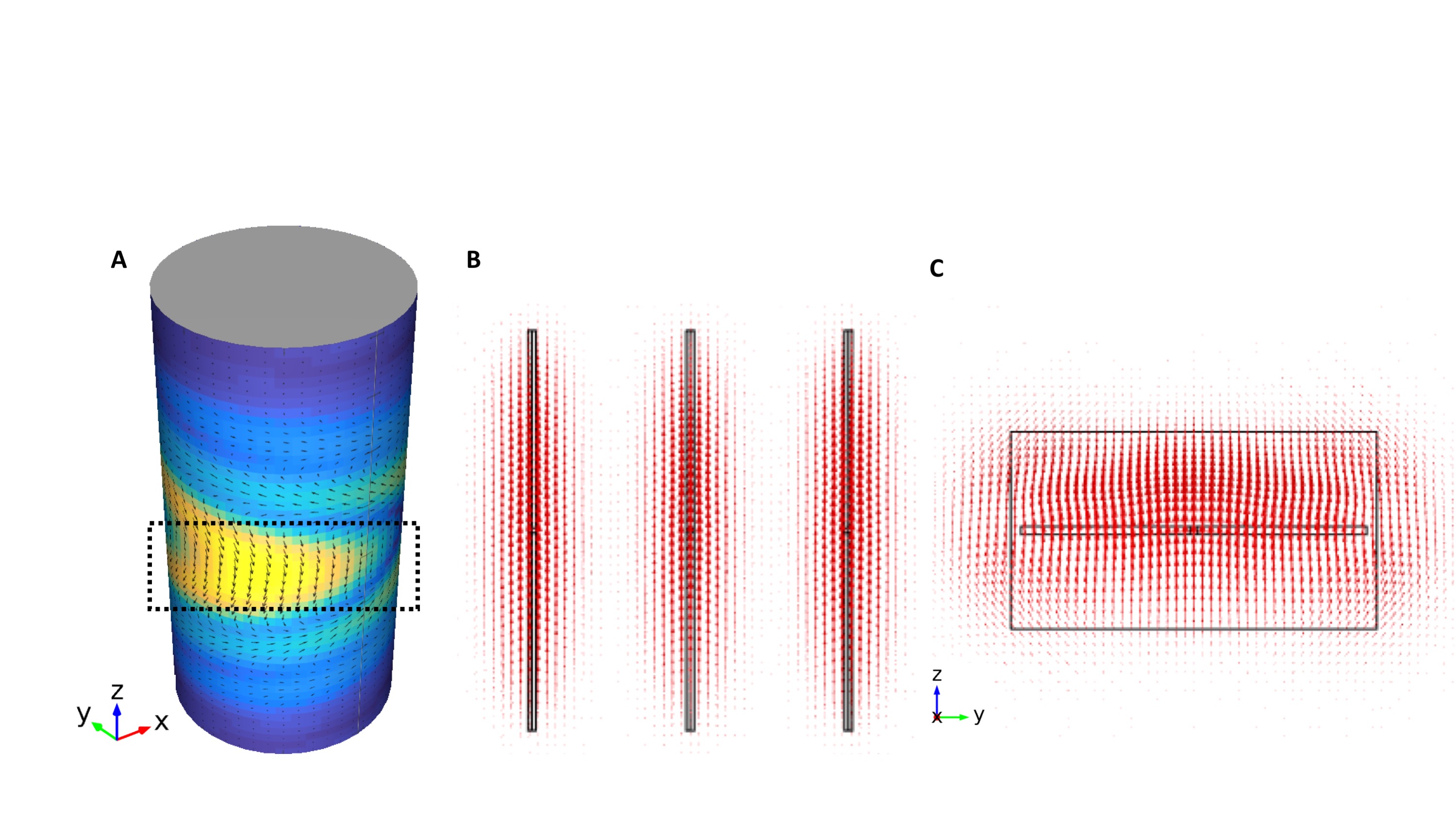
Ideal current patterns around the cylinder (A). E field pattern
generated by the three-dipole-antenna simulation (B) and slot antenna (C).
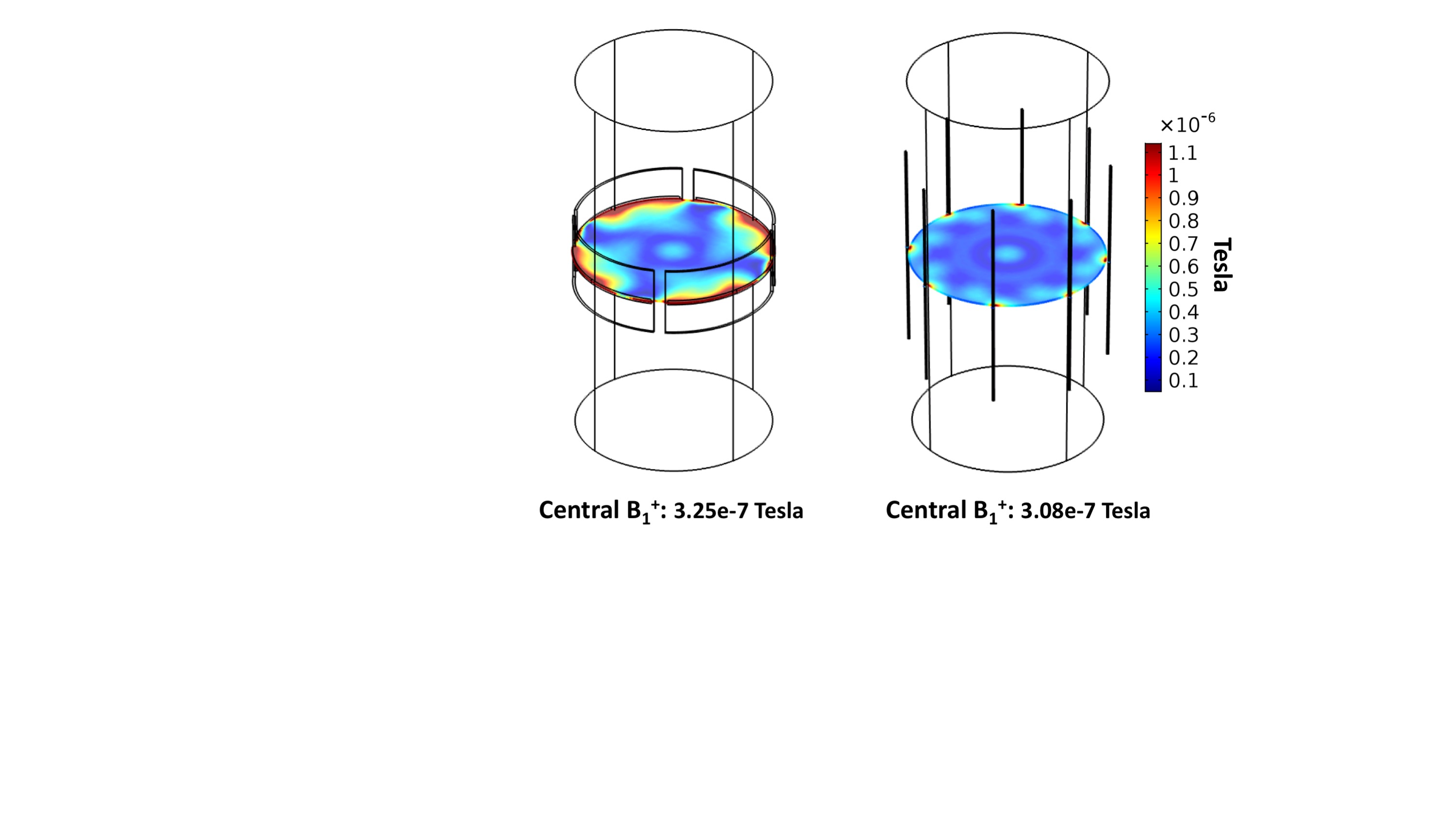
B1+ normalized by the square root of the power
deposition in the phantom for a 4-slot setup (left) and an 8-dipole setup
(right).