4314
29-channel Receive-only Dense Dipole Head Array for 7T MRI1Bernard and Irene Schwartz Center for Biomedical Imaging, Department of Radiology, New York University School of Medicine, New York, NY, United States, 2The Sackler Institute of Graduate Biomedical Sciences, New York University School of Medicine, New York, NY, United States
Synopsis
Inspired by recent theoretical work indicating that z-oriented currents could capture most of the optimal SNR and outperform loops in reception at high frequencies, we constructed and evaluated a close-fitting dense dipole receive-only head array with 29 elements. The array was combined with a dual-channel transmit birdcage for experiments. SNR was good throughout a head phantom at 7T and outperformed a commercial head coil in regions above and below the center. Future work will focus on detuning mechanisms for dipole elements to enable safe in-vivo measurements.
Purpose: A recent study showed that z-oriented currents can achieve over 90% of the ideal current patterns corresponding to the ultimate intrinsic signal-to-noise ratio (UISNR) in the center of a body-sized cylinder at 7T [1]. This suggests that a dense arrangement of z-directed dipoles could produce favorable signal reception at ultra-high fields. In fact, 7T simulations showed that a dense dipole array yields a larger central SNR in a cylindrical phantom than a loop-only array with the same number of elements [2]. However, there are challenges associated with the construction of a many-element dipole array, including arranging dipoles for minimal coupling and desired coverage, antenna detuning, and efficient means to shorten the antenna. Here we present a close-fitting 29-channel receive-only dense dipole array for brain imaging at 7T.
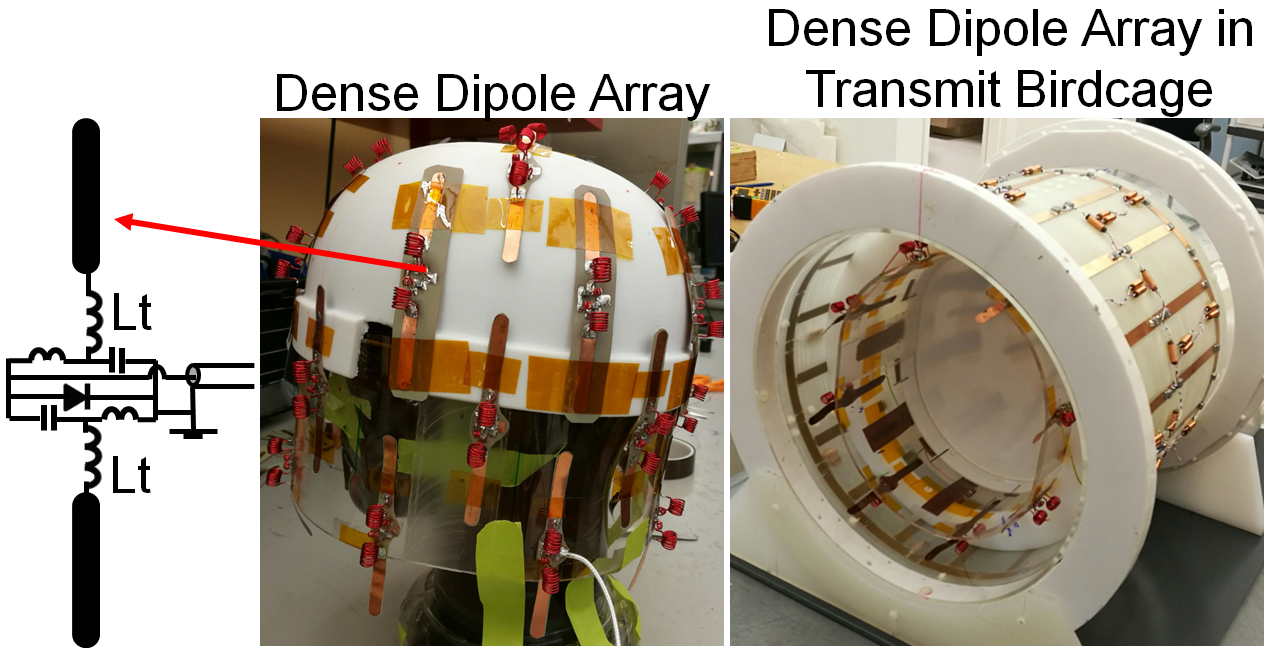
Methods: Twenty-nine inductively-shortened λ/2 dipole antennas were etched from paralux material. Each dipole element was 11cm long and 5mm wide. For frequency tuning, two inductors were placed symmetrically on each side of the port (Figure 1) while in the presence of a head-shaped gel phantom (εr=41, σ=0.39 S/m). A lattice balun was used to match and balance the current distribution, and a PIN diode across the ends of the balun was used to detune the diploes during transmission. Twenty-seven z-directed dipoles were placed on a close-fitting helmet (diameter=220mm, length=240mm) and arranged in four rows to provide full head coverage with four, eight, seven, and eight elements per row going from the head apex to the base. Elements in adjacent rows were staggered to minimize coupling [4]. Two extra crossed dipole antennas were placed at the top of the helmet to enhance sensitivity around the apex. Preamplifier decoupling was achieved by adjusting the coaxial cable length between the dipoles and preamplifiers located behind the array. A 16-rung high-pass birdcage coil (diameter=300mm, length=240mm, copper width=10mm) was constructed as a separate detunable transmit-only coil. The phases to the two birdcage ports were chosen to create constructive interference at the center of the phantom. A diode was placed at the center of each rung and end ring segment to detune the coil during reception. The dipole array was compared to a commercially-available head coil with a 24-channel loop array on a 7T scanner (Siemens Healthcare, Erlangen Germany). Flip angle maps were acquired with a turbo-flash B1-mapping sequence [4]. SNR maps were generated from 2D GRE acquisitions (TR/TE=4000/4.0ms, BW=300Hz/pixel, FOV=220×220mm, Matrix=128×128, slice thickness=5mm) with and without RF excitation [5].
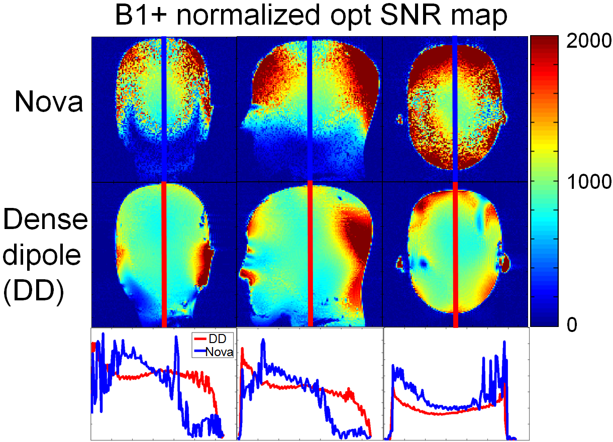
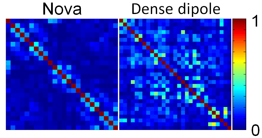
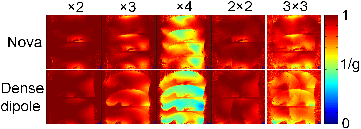
Results: The S21 between adjacent dipole elements was lower than -8.5 dB, and all elements were matched to -20dB or better. Dipole detuning provided a 20dB reduction in power induced in a double-pickup probe. As determined with S11 and S22 at the two ports to the birdcage coil, however, the dipole detuning state had little effect on the birdcage tune and match, resulting in relatively low transmit efficiency of the birdcage. Optimal SNR maps [5] (i.e. SNR obtained using matched filter combination of elements) normalized by the sine of the flip angle are shown in Figure 2. Central SNR (corresponding to mid-cerebrum) was 859 for the dipole array and 1129 for the Nova coil. SNR was 862 for the dipole array and 526 for the Nova coil in a region corresponding to skull base, and 794 for the dipole array and 141 for the Nova coil in a region corresponding to the upper cervical spine. The dense dipole array provided superior performance at the top of the phantom. The noise correlation matrices are shown in Figure 3. Inverse g-factor maps (Figure 4) showed comparable parallel imaging performance for the two arrays.
Discussion: The dense dipole array showed a relatively homogeneous sensitivity over the entire brain. The central SNR of the dipole array was lower than the Nova coil, likely due to losses introduced by the tuning inductors. However, while the sensitivity of the Nova coil dropped at inferior locations, the dipole array had a longer coverage range, providing high SNR throughout the head. The fact that a single detuning location at the dipole midpoints did not affect the tuning and matching of the birdcage suggests that it may be necessary to explore other arrangements for detuning to maximize transmit efficiency of the birdcage.
Conclusion: A 29-channel dipole head array was constructed to demonstrate the feasibility of a high performance dense dipole based receiver array for brain imaging at 7 Tesla. Encouraging results were acquired in initial phantom experiments. Future work will focus on the development of improved dipole detuning and coil loss minimizing mechanisms, and in-vivo experiments.
Acknowledgements
No acknowledgement found.References
[1] Sodickson DK, Proc. ISMRM 2016, p389;
[2] Chen G, Proc. ISMRM 2016, p168;
[3] Brown GH, Proc. IRE.22, 457-480, April 1934;
[4] Klose U, Med. Phys. 19 (4), 1992;
[5] Kellman P. MRM 54; 1439-1447 (2005)
Figures