4311
Software Synchronization of Independent Receivers by Transmit Phase Tracking1Electrical Engineering, Stanford University, Stanford, CA, United States, 2GE Healthcare, Aurora, OH, United States, 3Procyon Engineering, San Jose, CA
Synopsis
For add on receiver electronics, and wireless receiver coils, a major challenge is the synchronization of on-coil digitizers without a physical connection to the scanner. We propose that a digitizer that multiplexes the RF pulse and FID to an ADC can then use the transmit data to phase and frequency correct the MRI image data. We demonstrate frequency estimator and pulse sequence frequency tracking feasibility with a test bench that synthesizes the wireless MRI data acquisition and artifact-free image reconstruction.
Introduction
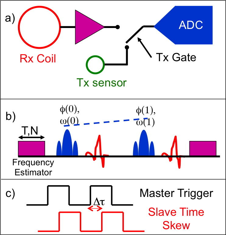
Parallel imaging is driving trends to more channel counts than ever before, but at a cost of significant infrastructure complexity, and costly upgrades. A solution to alleviate the bulk and added cable complexity, via wireless receiver coils, has long been considered a "Holy Grail" for coil design. If data are digitized on-coil, modern WiFi standards (802.11ac,ad) appear capable of supporting MRI data rates. But without a physical connection, how does one ensure sampling clocks are synchronized? One option is to transmit small signal pilot tones during receive [1], another to transmit the physical clock signal via antennas, but both require significant scanner re-engineering. We hypothesize that the MRI transmit signals can provide phase/frequency references to phase correct data, using B1+ sensor-loops and preamps multiplexed to free-running digitizers (Fig. 1). Here, we demonstrate software re-synchronization feasibility.
Theory
If a free-running receiver can digitize the RF pulse waveform, inevitably, it will be offset in phase, frequency, and trigger time delay. A first option is to insert "do-nothing" low-level, off-resonant RF tones in pulse-sequence dead-times to provide sinusoid frequency tracking. By least squares fits to unwrapped time domain signals[2-4], or interpolating a truncated DFT[5,6] (Fig. 2), frequency and phase can be estimated to the Cramer-Rao bound:
$$\sigma^2_f =\frac{\sigma^2}{A^2}\frac{6}{4\pi^2T^2N(N^2-1)}, ~~~ \sigma_\phi^2=\frac{\sigma^2}{A^2} \frac{2}{N}$$,
eg. an N=256 sample, T=4.1 ms tone of A/σ=100, can estimate to 60 mHz even though the DFT bin is 244 Hz.
Second, a digitized RF pulse $$$|s(t)|e^{j\phi(t)}$$$ can be processed for trigger skew, and phase/frequency offsets. Since the RF pulses have common envelopes, frequency/time shift is embedded in the opposing Fourier domain phase ramp only. Offset frequency is determined by the time-domain unwrapped phase slope of a Sinc central lobe, and time skew from the DFT slice profile S(f) phase ramp. Alternatively the center of energy's (COE) of |s(t)|, |S(f)| provide similar results:
$$\Delta f = \frac{\int f|S(f)|^2df}{\int |S(f)|^2df}~~~\Delta t = \frac{\int f|s(t)|^2dt}{\int |s(t)|^2dt}$$
Phase offset is computed from the mean of slice profile central phase. These basic estimator blocks can then be employed to track timing and phase drift over the duration of a pulse sequence to correct k-space data.
Methods
To test feasibility, we used a pair of Medusa[7] consoles, one acting as master, and the second, a slave operating off separate 50 MHz sampling clocks. The master was programmed to play out an MRI pulse sequence, as well as synthetic k-space data which was looped-back to its receive port. The slave also digitized the synthetic data upon triggering from the master. Two test sequences were performed, both using TR=150ms, 256x256 data, 62.5kHz readout bandwidth, and 3 ms windowed Sinc's of TBW 4. In the first, the k-space data were constant tones, which should lead to an "impulse" image. These tones allowed comparison of sinusoid frequency estimators to those from RF pulse frequency estimation. The second sequence transmitted a MRI phantom k-space data and used only RF pulse data for receiver time, frequency and phase correction. Local RF pulse frequency estimators were extrapolated with neighboring pulses to give a larger time window for improved frequency tracking.
Results
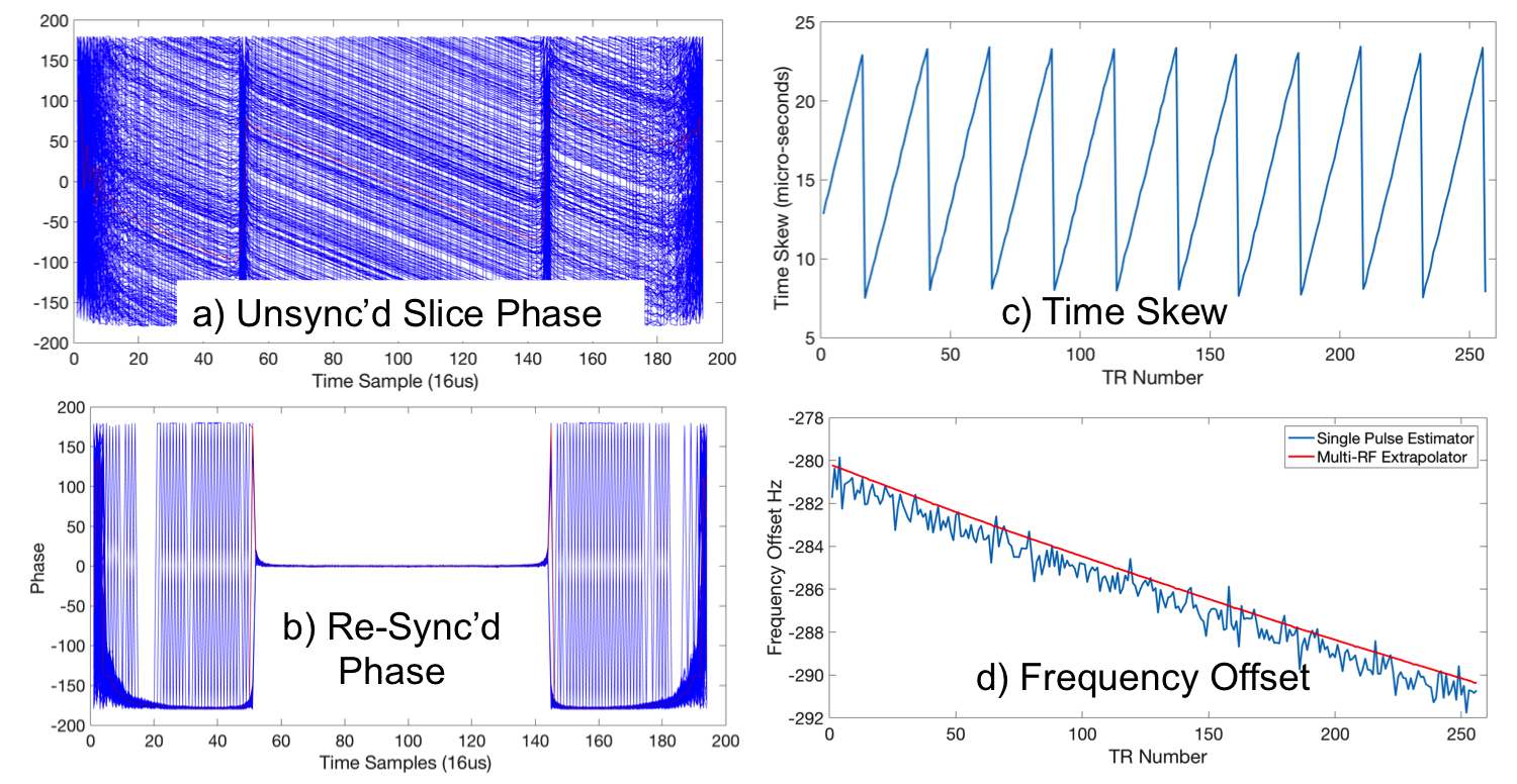
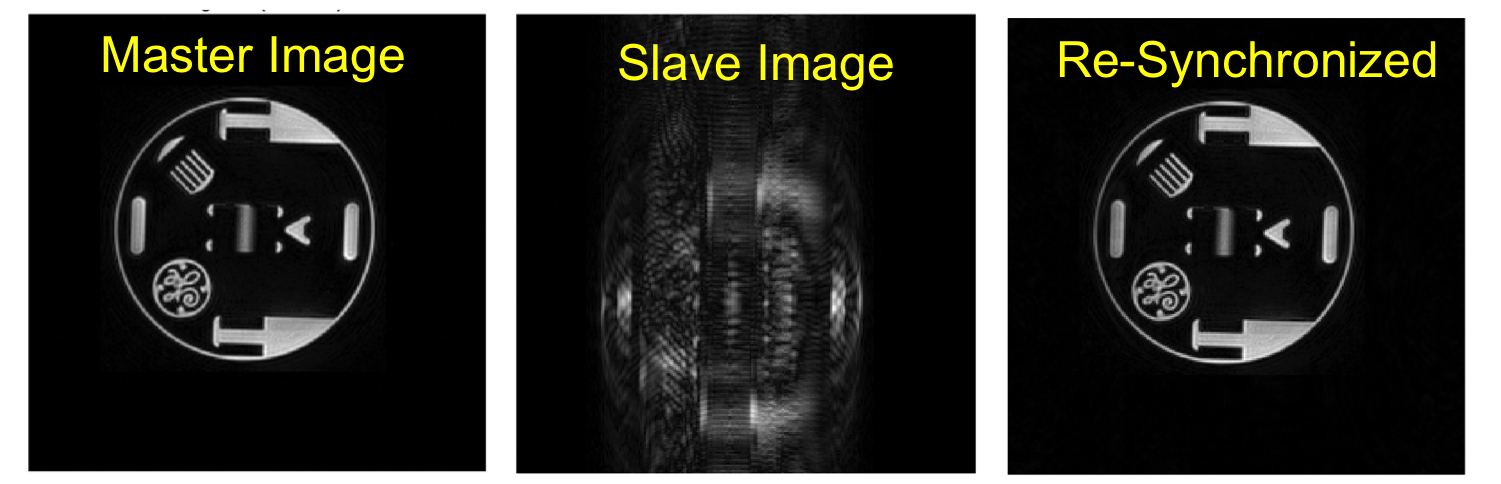
Figure 3 shows the data steps for the unsynchronized slice data, and the extraction of time skew, frequency and phase, resulting in resynchronized slices. Figure 4 applies these corrections to the unsynchronized slave image, yielding a re-synchronized data. The master loop-back image is shown for reference. Figure 5 compares the tone frequency estimators with those derived from RF pulse offsets and from extrapolated estimates. COE and central lobe temporal phase ramp estimates of frequency are noisy, predicting -310Hz. Even so, this was sufficient to extrapolate to the next RF pulse with the correct phase wrap guess, so a higher time fit could be used.
Discussion & Conclusion
In MRI, the RF pulses will have very high SNR such that a 1cm diameter pickup loop would suffice. These tests have shown that transmit waveforms, and frequency estimator tones embedded with a pulse sequence, suffice to reconstruct phase corrected images from from receivers with no clock synchronization. One caveat is that the slave clock cannot be perturbed by the MRI gradients (voltage controlled oscillator dB/dt modulation, crystal microphonics) or RF (injection locking). If possible, this method creates an interesting option for third parties to expand the receive channel count with access to little more than a transmit Q-spoil trigger. It also provides a path for wireless receiver coils to exploit the transmit signal, which always exists to re-synchronize with the scanner without major modification to the scanner.
Acknowledgements
We would like to thank Thomas Grafendorfer of GE Healthcare for useful discussions.
Grant Support: GE Healthcare, NIH R01EB019241.
References
[1] Bosshard J, et al, Phase Correction with Asynchronous Digitizers, ISMRM 23, 2015
[2] S. Tretter, " Estimating the frequency of a noisy sinusoid by linear regression." IEEE Trans. Info. Theory 31, pp832-835, 1985.
[3] S. Kay, " A fast and accurate single frequency estimator." IEEE Trans. Acoustics Speech, Signal Process. 37, pp1987?1989, 1989.
[4] M.L. Fowler, "Phase-Based Frequency Estimation: A Review", Digital Signal Processing, 12, pp. 590-615, 2002.
[5] B. Quinn, "Estimation of Frequency, Amplitude and Phase from the DFT of a Time Series," IEEE Trans. Signal Processing, vol. 45, No. 3, March 1997, pp. 814-817.
[6] M. Macleod, "Fast Nearly ML Estimation of the Parameters of Real or Complex Single Tones or Resolved Multiple Tones", IEEE Trans. Signal Processing, 48, pp 141-148, 1998.
[7] Stang P, et al, Medusa: A Scalable MR Console Using USB, 2012
Figures
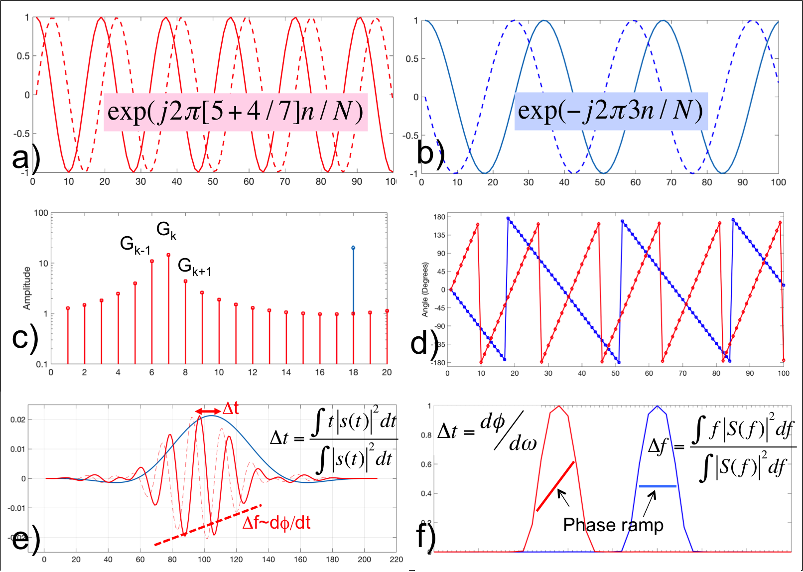

Frequency Estimator Comparisons. Here, constant tones were transmitted for phase-based Frequency estimation (blue). The RF pulse Sinc phase-ramp estimate (magenta) and slice profile COE (red) are too noisy for high accuracy. However they can be used to properly connect multiple RF pulse phase data to attain a high accuracy frequency estimate.