4309
Optimization of the Receive Performance of a Tight-Fit Transceiver Phased Array for Human Brain Imaging at 9.4T.Nikolai I. Avdievich1, Ioannis A. Giapitzakis1, and Anke Henning1,2
1Max Planck Institute for Biological Cybernetics, Tübingen, Germany, 2Institute of Physics, Ernst-Moritz-Arndt University, Greifswald, Germany
Synopsis
Tight-fit ultra-high field (UHF) (>7T) surface loop transceiver (TxRx)-phased arrays improve transmit (Tx) efficiency in comparison to Tx-only arrays built larger to accommodate for receive (Rx)-only array inserts. However, the number of elements in TxRx-arrays is restricted by the number of available RF Tx-channels (commonly 8 or 16), which limits the Rx-performance. A prototype of a 16-element array, which consists of 8 TxRx-surface loops circumscribing a head and 8 additional “vertical” Rx-only loops positioned in the center of each TxRx-loop perpendicularly, was constructed. This addition improves the Rx-performance substantially and has a minimal effect on both the Tx-efficiency and maximal local SAR.
Introduction:
Tight-fit human head ultra-high field (UHF, 7T and above) transceiver (TxRx) surface loop phased arrays (1,2) improve transmit (Tx) efficiency in comparison to Tx-only arrays, which are usually larger to fit multi-channel receive (Rx)-only arrays inside (3). A drawback of the TxRx-design is that the number of array elements is restricted by the number of available radiofrequency (RF) Tx-channels (commonly 8 or 16). This channel count is not sufficient for an optimal SNR and parallel Rx-performance. In this work we developed a method of increasing the number of Rx-elements in a TxRx-array without the necessity of moving the Tx-elements further away from the subject, which compromises the Tx-performance. We designed and constructed a prototype of a 16-channel human head phased array, which consists of 8 TxRx-surface “horizontal” loops circumscribing a head, and 8 Rx-only “vertical” loops positioned along the central axis (parallel to B0) of each TxRx-loop perpendicularly to its surface.Methods:
The array consists of 8 overlapped horizontal (10.5 cm in width; 10 cm in length) TxRx-loops, and 8 vertical (3.3 cm x 10 cm) Rx-only loops (Fig.1) and measures 20 cm in width (left-right) and 23 cm in height (anterior-posterior). Overlapping of adjacent horizontal loops provides excellent decoupling below -30 dB (Fig.2) (4). All vertical loops are decoupled by preamplifier decoupling during reception and actively detuned during transmission. The array is shielded with a cylindrical shield at 4-cm distance to the coil elements. Electromagnetic simulations of the transmit B1+ field and the local specific absorption rate (SAR) were performed using CST Studio Suite 2015 (CST, Darmstadt, Germany) and the time-domain solver based on the finite-integration technique (FIT). We also included vertical Rx-only loops into simulations since the presence of actively detuned Rx-only elements may substantially alter the maximal local SAR (5). Three voxel models were used, i.e. a head/shoulder (HS) phantom (3), which was constructed to match tissue properties (ε = 58.6, σ =0.64 S/m at 400 MHz) (3), and two virtual family multi-tissue models, “Duke” and “Ella”. Experimental B1+ maps were obtained using the AFI sequence (6). All data were acquired on a Siemens Magnetom 9.4T human imaging system.Results and Discussion:
First we performed a safety evaluation of the array including EM modeling (B1+, SAR) and phantom imaging. Simulations showed that the maximum local SAR was increased by less than 3%, and B1+ efficiency decreased by less than 1% due to introduction of the vertical loops. Then we conducted in-vivo experiments (Fig.3). Averaged over the 20-mm central slab B1+ measures 12.4 ± 2.7 μT/√kW in case of the 16-channel design versus 12.5 ± 2.8 μT/√kW in case of the 8-channel design. Introduction of the vertical Rx-only loops improved the in-vivo SNR near the coil center by ~28% and at the periphery by ~30% to 40%. Finally we compared parallel Rx-performance of the 16-channel array with that obtained using 8 horizontal loops only (Table 1). As an example Fig.4 demonstrates transversal G-factor maps obtained near the array center. At high acceleration (AF=5) the 16-channel mode improves an average G-factor up to 20% for an acceleration in the AP-direction. An idea of combining vertical and horizontal loops is similar to a recently proposed method of combining dipole antennas with surface loops to provide for better SNR (7). According to an ultimate intrinsic SNR approach, a combination of the curl-free and divergence-free currents on a cylindrical surface is required to produce an optimal SNR (8,9). In our case the curl-free current component is produced by vertical loops, which are easier to construct in terms of matching, tuning, decoupling, and active detuning, than dipole antennas.Conclusion:
As a proof of concept we developed a method of increasing the number of Rx-elements in a human head transceiver array without the necessity of moving the transmit loops away from the subject head and thus compromising the Tx-efficiency. We constructed a prototype of a 16-channel 9.4T tight-fit head phased array, which consists of 8 horizontal TxRx-surface loops circumscribing a head, and 8 Rx-only vertical loops placed at the center of each TxRx-loop. We demonstrated both experimentally and numerically that addition of the vertical loops substantially improves the Rx-performance without compromising the Tx-performance and the maximum local SAR. To further improve SNR and the longitudinal coverage along the array axis, increasing the overall number of array elements, (i.e. double-row 16-TxRx-element and 32-Rx-element array) is required.Acknowledgements
No acknowledgement found.References
References: 1) Gilbert KM et al, MRM 2010;67:1487. 2) Avdievich NI et al, Proc.ISMRM 22,2014,622. 3) Shajan G et al, MRM 2014;71:870. 4) Avdievich NI et al, Proc.ISMRM 24,2016,169. 5) Krishnamurthy N et al, JMRI 2014;39:475. 6) Yarnykh VL. MRM 2007;57:192. 7) Chen G et al, Proc.ISMRM 23,2015,3133. 8) Lattanzi R et al, MRM 2012;68:286. 9) Pfrommer A et al, Proc.ISMRM 24,2016,175.Figures
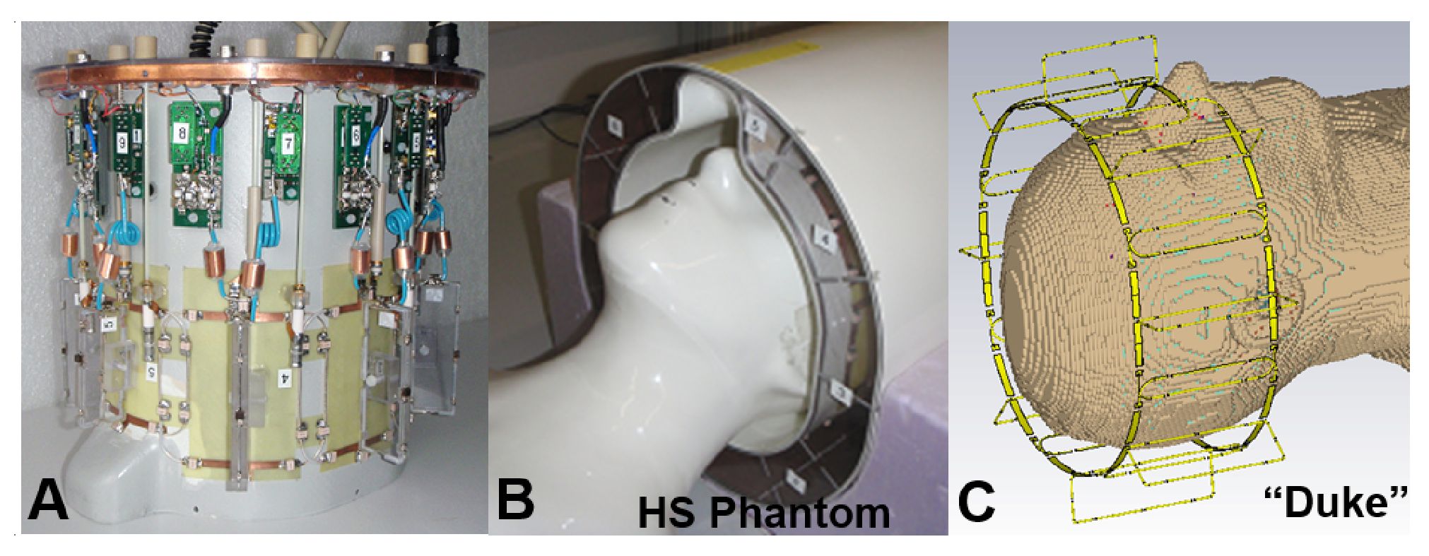
Figure 1. Photos of the phased array (A) without the cover,
(B) with the cover on and HS phantom inside. C) CST model of the phased array loaded by
the "Duke" voxel model. Lumped elements and ports
are not shown.
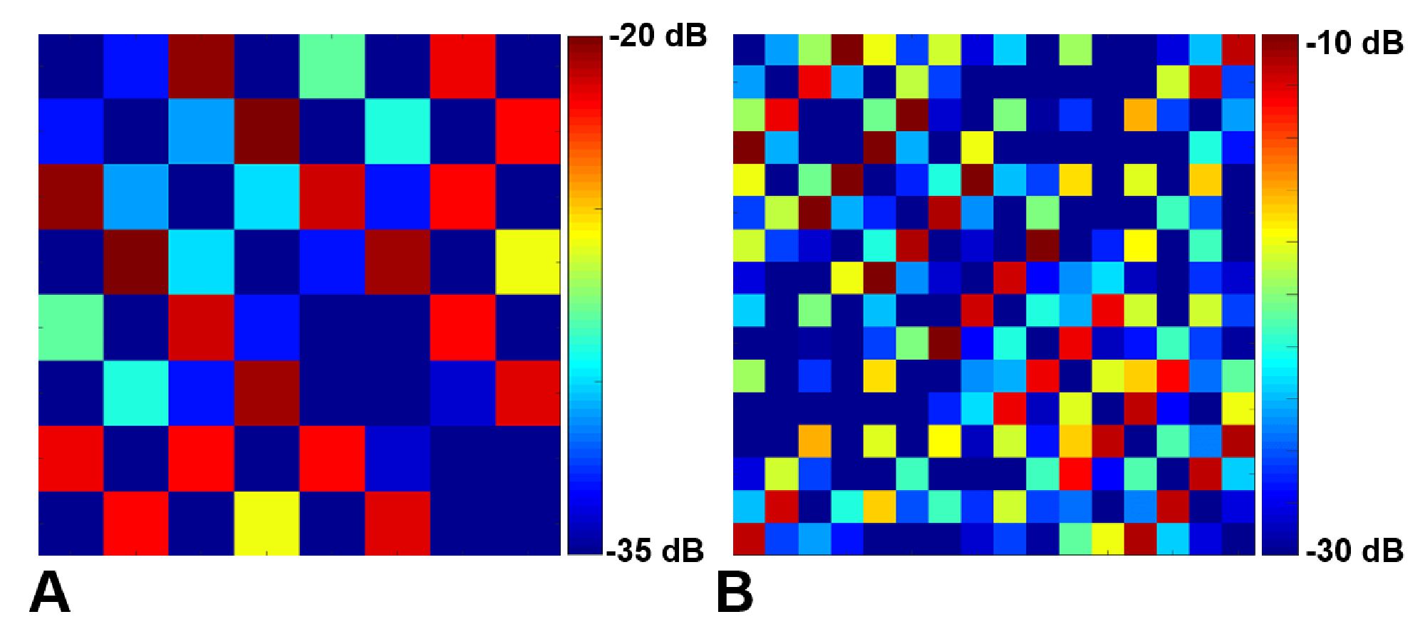
Figure 2. A) S12 matrix
measured for the 8-channel transceiver array (horizontal loops) loaded with
the HS phantom. For S12 matrix measurements all vertical loops were
actively detuned. B) Noise correlation matrix measured for all 16 loops using
the HS phantom.
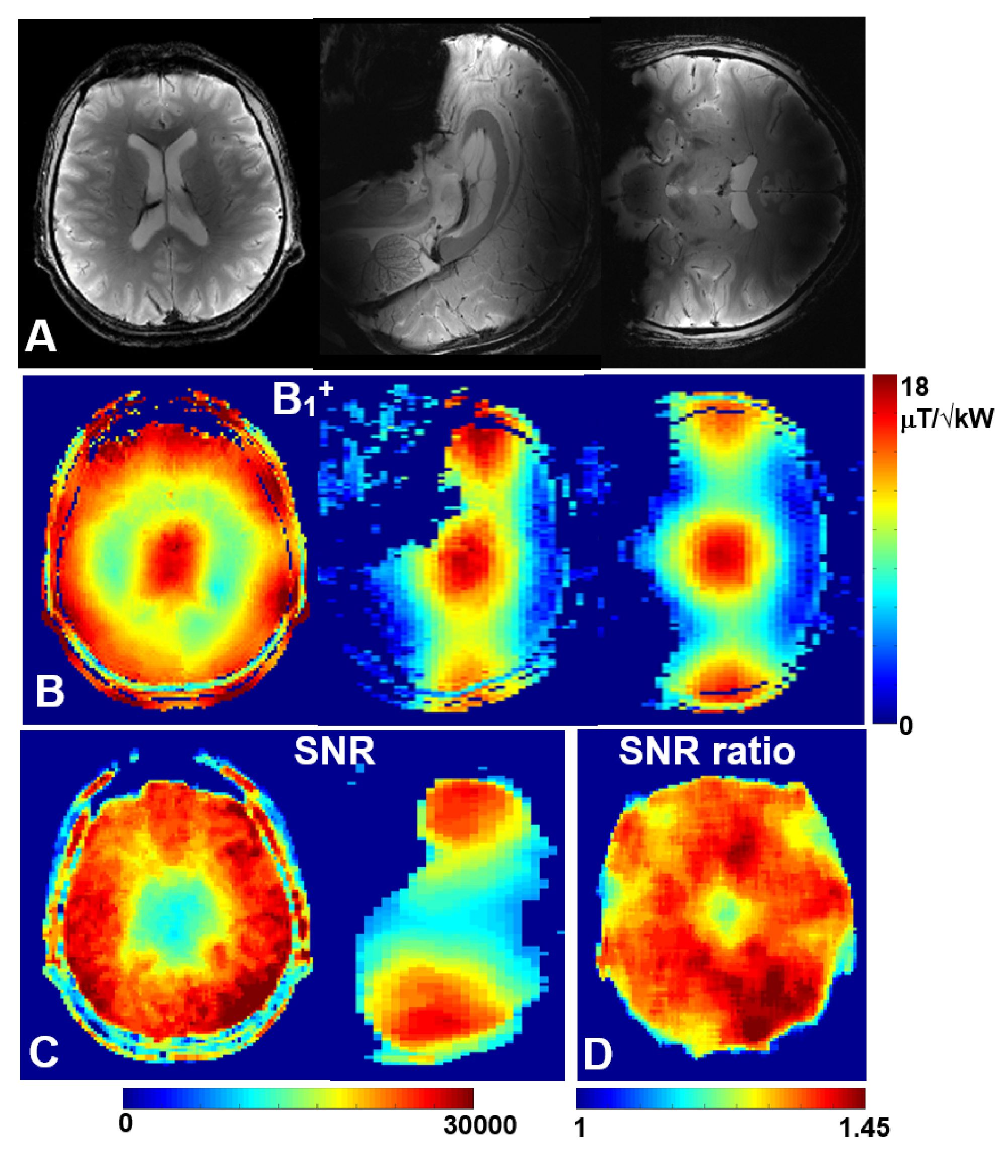
Figure 3. A) Central transversal, sagittal, and coronal
in-vivo GRE images obtained using all 16 channels. B1+
(B) and SNR (C) maps obtained for slices shown in Fig.3A. D) The averaged ratio
of the in-vivo SNR obtained using all 16-channels to the SNR of 8 TxRx-loops
only. The ratio is averaged over the central 20-mm transversal slab.
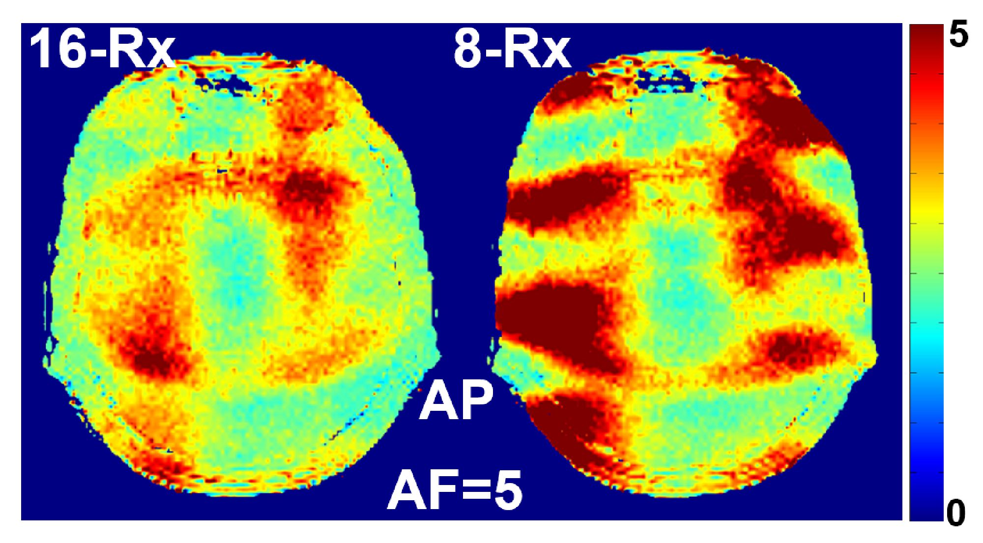
Figure 4. In-vivo G-factor transversal maps obtained using
the array in 16-channel and 8-channel reception modes. Both maps were
acquired with AF = 5 and acceleration in the AP direction.
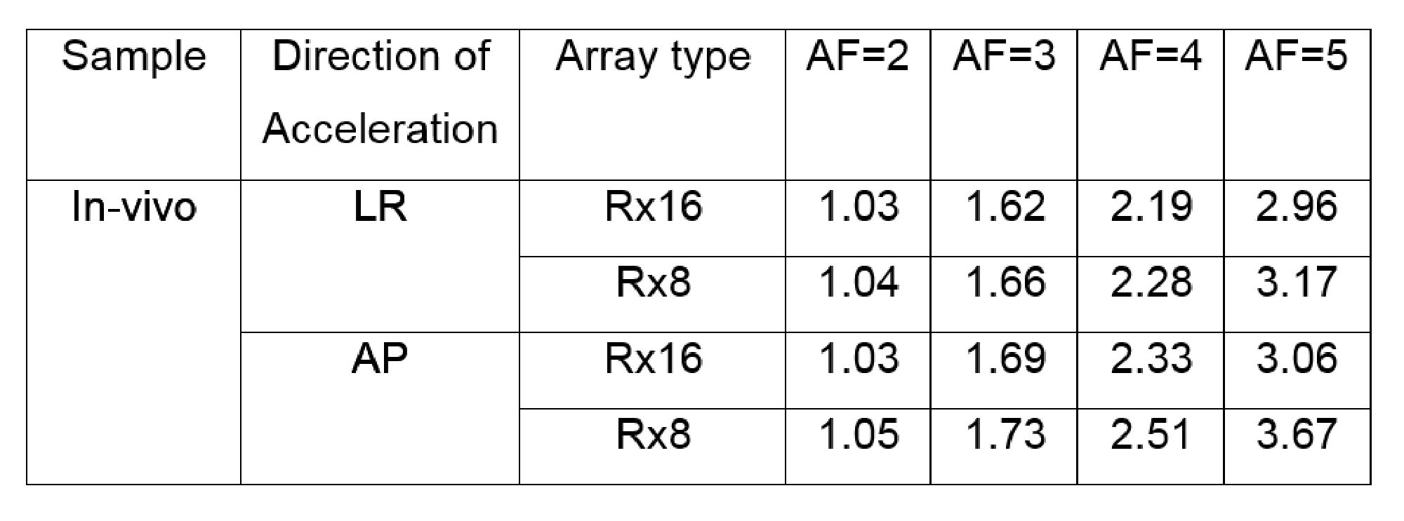
Table 1. In-vivo average
G-factors.