4306
Comparison of a 32-channel remote body coil for 7 Tesla with local and remote 8- and 16-channel transmit coil arrays1Medical Physics in Radiology, German Cancer Research Center (DKFZ), Heidelberg, Germany, 2Erwin L. Hahn Institute for MRI, University Duisburg-Essen, Essen, Germany, 3High Field and Hybrid MR Imaging, University Hospital Essen, Essen, Germany
Synopsis
The RF shimming performance of a 32-channel remote body coil is compared to ideally and non-ideally decoupled local and remote arrays consisting of 8 and 16 channels by evaluation of the singular values as well as evaluation of the RF shimming performance in axial and coronal slices with L-curves. For high-field body imaging, multi-ring remote coil arrays provide high degrees of freedom for RF shimming and can achieve higher B1+ homogeneity, especially for coronal slices. However, to utilize the full RF shimming potential of remote multi-ring transmit arrays, high local SAR has to be taken into account during safety assessment.
Introduction
pTx systems with multi‐channel transmit arrays provide higher degrees of freedom (DOF) for the manipulation of RF fields. Predominantly local RFcoil arrays placed directly on or close to the subject are used. In contrast, remote coil arrays placed on the bore liner allow for a higher number of coil elements and provide superior patient comfort as well as a larger field of view. In this simulation study, the RF shimming performance of a 32-channel (32-ch) remote body coil1 is compared to local and remote coil arrays consisting of 8 and 16 channels.Methods
Fig. 1 shows the investigated remote and local body arrays, each consisting of meander stripline elements (length 25 cm)1 and loaded with a heterogeneous body model (male, 174cm, 72.4kg)2 in head-first supine position with the liver-kidney region in coil center. All array configurations were ideally decoupled3,4. In addition, the 32-ch, 8-ch local and 8-ch remote array configurations were investigated with non-ideal decoupling. For the 32-ch coil, the physically implemented decoupling network1, which decouples nearest and next-nearest neighbors by a network of capacitors and transmission lines, was considered in the simulation model. For the 8-ch arrays, no decoupling network was required due to the strong coupling to the body model for the local array and the quite large distance between the elements in the remote array. B1+ maps were extracted for the individual channels, and SAR matrices based on the VOP algorithm5 were computed. As a measure for the available DOF of the individual arrays, the normalized cumulative sum of the singular values of the 3D complex B1+ maps were evaluated6 in a region of interest (ROI) with length of 50 cm encompassing the cross-section of the body model excluding the arms. RF simulations were performed in CST Studio Suite7.
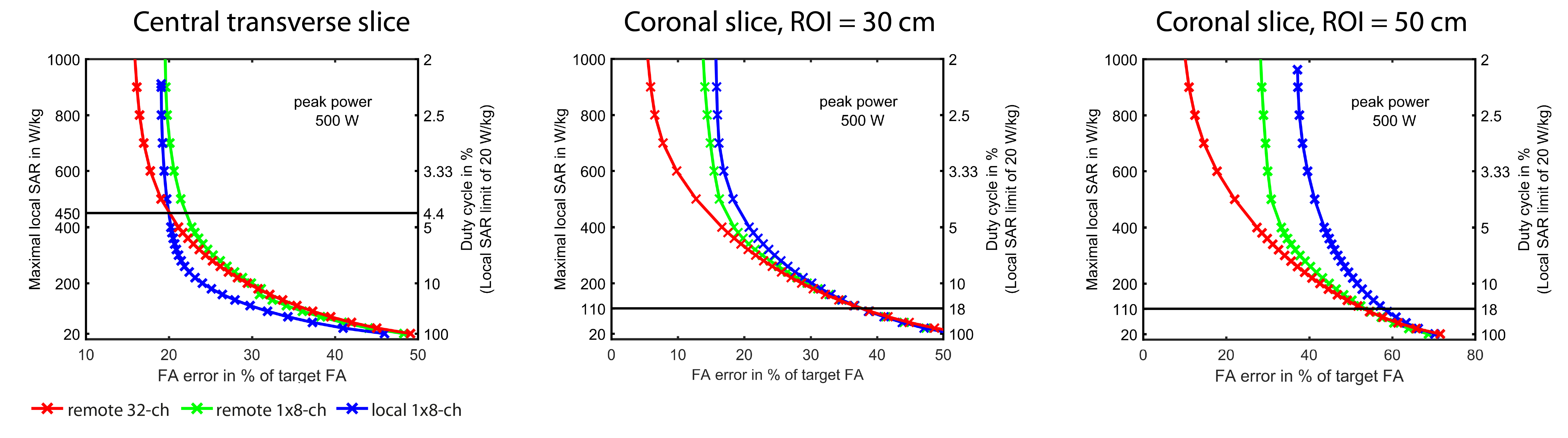
RF shimming regarding uniform B1+ was conducted in central axial and coronal slices based on the approach presented in 8 for a target magnetization of 6.5 µT and a constraint for peak power per channel of 500 W. For the coronal slice, ROIs with lengths of 30 cm and 50 cm along the longitudinal axis were used. For the SAR evaluation, a duty cycle was not taken into account, but results are also presented in terms of the permissible duty cycle at which the local SAR limit is not exceeded.
Results and discussion
Figure 2 shows the cumulative sum of the singular values. In general, uncorrelated B1+ fields would result in a cumulative sum equal to the number of elements. Instead, the fields significantly overlap and thus the cumulative sums are considerably smaller. The multi-ring arrays did not show a plateau even for a high number of elements, indicating that placing elements along the longitudinal axis is beneficial. However, adding more than 10-12 elements in 1 ring does not significantly increase the shimming performance.
RF shimming results are presented as L-curves. For all configurations the maximum local SAR was located in the arms. Thus, the SAR limit in the limbs in normal operating mode (20 W/kg) was considered for the determination of the permissible duty cycle. In Figure 3 the maximum local SAR for a given flip angle (FA) error is shown for non-ideal decoupling. For the axial slice, the 32-ch array achieves lower FA errors and outperforms the other arrays for protocols with duty cycles up to 4.4%. However, for more SAR-demanding protocols, the local 8-ch array achieves the lowest FA errors. In coronal slices, the 32-ch array shows superior RF shimming performance and achieves lower FA errors up to a duty cycle of 18%. This finding becomes more evident for larger FOV.
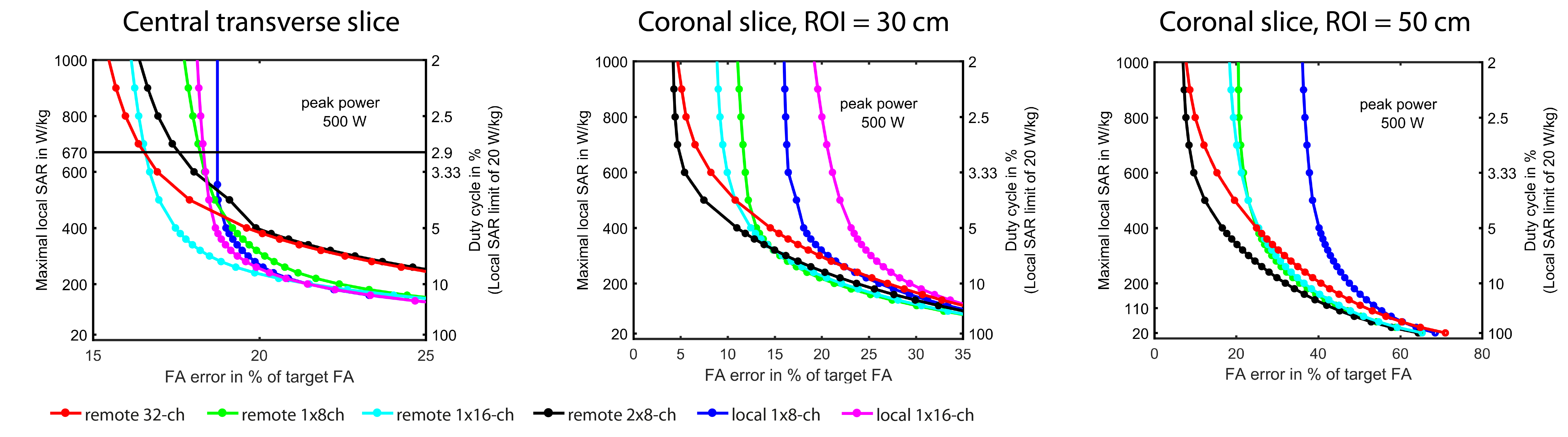
For comparisons including the 16-ch arrays, ideal decoupling networks are considered. In the transversal slice, the 32-ch array shows the lowest FA error for duty cycles lower than 2.9% followed by the remote 1x16-ch array, Fig. 4. For the coronal slice, the 2x8-ch array shows the highest performance, while the 32-ch array achieves a similar performance for duty cycles lower than 2%.
Conclusion
Coil elements arranged in multiple rings offer more DOF for RF shimming in the longitudinal direction. Remote arrays can achieve lower FA errors and outperform the local arrays considered in this study due to higher DOF, as shown for coronal orientations. However, to unlock the full RF shimming potential of remote transmit arrays with high channel count for body imaging at 7T, a low duty cycle or a high SAR level has to be taken into account. A more detailed safety assessment based on temperature and thermal dose could allow for higher input powers.Acknowledgements
The research leading to these results has received funding from the European Research Council under the European Union's Seventh Framework Programme (FP/2007-2013) / ERC Grant Agreement n. 291903 MRexcite.References
1. Orzada et al. Proc. ISMRM 24 (2016) #0167
2. Christ et al. (2010). Phys. Med. Biol. 55(2):N23-38
3. Mahmood et al. Proc ISMRM 21 (2013) #2722
4. Mahmood et al. Proc ISMRM 22 (2014) #0584
5. Eichfelder and Gebhardt. MRM 66:1468-1467 (2011)
6. Guérin et al. MRM 73:1137-1150 (2015)
7. CST Studio Suite 2016, CST AG, Darmstadt, Germany
8. Flöser et al. Proc. ISMRM 23 (2015) #0550
Figures
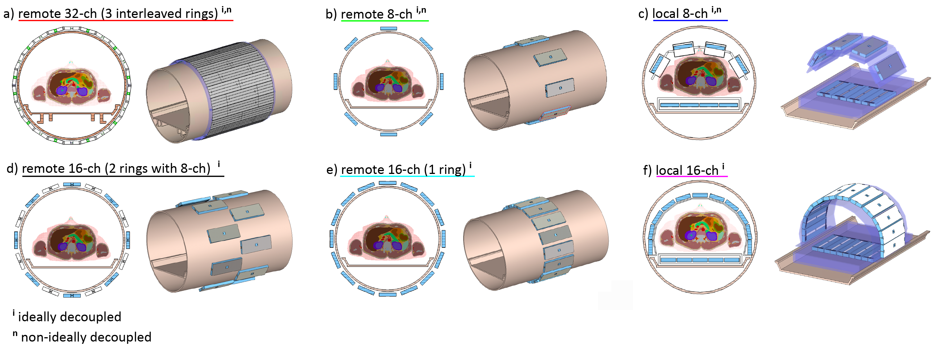
Figure 1: Remote arrays placed on the bore liner in the configurations a) 32-ch (3 interleaved rings of 10, 12, and 10 elements, overall length: 60 cm), b) 1x8-ch (1 ring of 8 elements), d) 2x8-ch (2 rings of 16 elements, overall length: 50 cm), e) 1x16-ch array.
Local arrays consisting of 1 ring placed close to the subject in the configurations c) 1x8-ch, and f) 1x16-ch array. Outer MR environment not visible but included in the modeling.
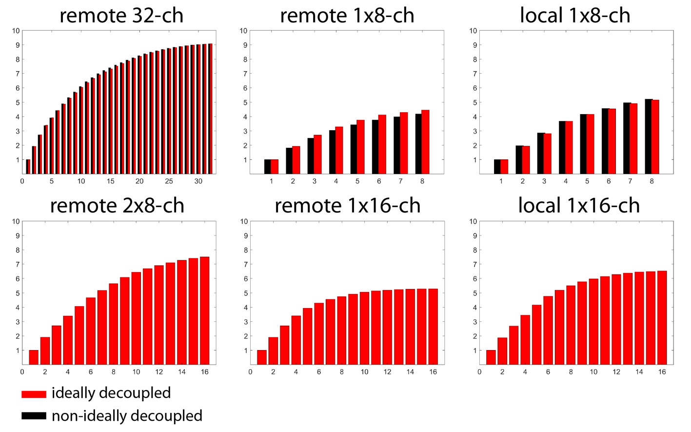
Figure 2: Comparison of the cumulative sum of the singular values for the 3D complex B1+ maps evaluated in a ROI with length = 50 cm along the longitudinal axis (arms excluded).
Red bars: ideally decoupled arrays, black bars: non-ideally decoupled arrays.