4304
32-Channel In-Vivo Parallel Transmit Body Imaging at 7 Tesla1Erwin L. Hahn Institute for MRI, University Duisburg-Essen, Essen, Germany, 2High Field and Hybrid MR Imaging, University Hospital Essen, Essen, Germany, 3Division of Medical Physics in Radiology (E020), German Cancer Research Center (DKFZ), Heidelberg, Germany
Synopsis
In this work we present phantom and in-vivo pTx excitation results acquired with a 32-channel add-on pTx system based on a 1-channel 7T MRI system. The add-on system uses custom-built I/Q modulators and custom-built amplifiers located inside the magnet room. The single exciter channel is split into 32 sub-channels, whereby the modulators control the phase and amplitude of the individual pTx RF pulses. The modulators and pre-calculated pTx gradients are synchronized via trigger signals generated in the imaging sequence. With the 32-channel pTx system, reduced FOV imaging of the lumbar vertebrae during free breathing was possible.
Purpose
Parallel transmission (pTx)1,2 is a promising technique offering a variety of applications such as arbitrarily shaped excitation or reduced field of view imaging. Especially at ultra-high field, pTx may be helpful to counter the inherent B1 field inhomogeneities. In this work we present phantom and in-vivo results acquired with a 32-channel add-on pTx system based on a 1-channel 7T MRI system.Methods
The exciter channel of the 7T whole-body system (Magnetom 7T, Siemens, Erlangen, Germany) is split into 32 sub-channels by signal splitters utilizing microstrip circuit technology with industrial surface-mounted power divider components. One I/Q modulator per channel is used to modulate the signal coming from the system’s exciter,3 and these are fed into 32 custom-built amplifiers located inside the magnet room.4 The modulators are controlled via a 32-bit National Instruments digital I/O card and a customized GUI. A custom-built 32-channel integrated body coil was used.5,6
All settings that are necessary for one sequence run, i.e. all modulator settings, are loaded onto the card in advance, which then is synchronized to a trigger signal controlled by the MR sequence. The complete amplitude and phase sequences of the individual pTx RF pulse shapes are transformed into data words as needed for the communication with the modulators and downloaded onto the modulators within a few milliseconds before sequence begin.7
A gradient echo sequence was modified to play out calculated pTx RF pulses and the corresponding gradient samples. Also, excitation and readout orientation can be chosen independently. Due to modulator offsets, a modulated pTx pulse is played out on the exciter channel by the sequence that always applies the maximum amplitude over all individual RF pulses, thereby generating a variable dynamic range that minimizes the offset and digitization errors.7
A delay between gradient and RF system was corrected by shifting the exciter RF pulse 4 µs relative to the gradients.
As the total number of trigger events is restricted by the system architecture and the minimum trigger duration is 10 µs, the sequence can only play out trigger pulses every 20 µs. To enable 10 µs pulse sampling, the trigger events are duplicated by a custom-built hardware device consisting of two monostable multivibrators, with one of these acting on the rising edge and one acting on the falling edge. This hardware thus forms a trigger pulse with 2.5 µs length every 10 µs.7 The first trigger is issued 20 µs before the start time of the RF/gradients.
B1+ maps were acquired by using the B1TIAMO8,9 sequence that consists of fast measurement of relative maps acquired in an interleaved manner. These are normalized through the use of two absolute flip angle maps acquired by the pre-saturation method and applying two complementary shims. B0 mapping was also included in this sequence.
A custom-built SAR supervision system observed the magnitude of the forward power per channel with 1 µs sampling and provided 10 s and 6 min averages.
A 2D spiral gradient with variable density was used for calculation of non-selective RF pulses. For imaging the chosen orientation for excitation was axial while readout/phase encoding was performed in coronal orientation. Thus, the readout direction could be aligned with the longest axis of the phantom/healthy volunteer for faster 3D image acquisition. Imaging parameters can be found in the figure captions.
Results
In Figure 1 results in the body phantom are shown. Although the pTx pulse calculation is based on B0/B1 of a single central slice, the stability of the non-selectively excited pattern is quite stable throughout the whole phantom (Fig. 1B). The preparations for an in-vivo measurement are shown in Figure 2. Figure 3 compares breath hold and free breathing during a pTx excitation targeting the spinal column to free breathing during a GRE sequence using TIAMO9. Further in-vivo results are shown in Figure 4, including reducing the FOV during free breathing. Maximum input power per channel was below 2.5W (10s average), and mean input power was below 1W (10s average).Discussion
Total pulse duration at the moment is limited to < 8 ms due to the limited number of trigger events within the sequence. The background suppression of the applied pTx pulse was sufficient for reduced FOV imaging; however, it could presumably be improved by incorporating gradient trajectory imperfections (i.e. deviations from the trajectory used for calculation). Using B1/B0 information at multiple positions could improve the quality of the pTx pulse in the upper third of the 500 mm FOV the body coil provides.Conclusions
With the 32-channel pTx system, reduced FOV imaging of the lumbar vertebrae during free breathing is feasible.Acknowledgements
The research leading to these results has received funding from the European Research Council under the European Union's Seventh Framework Programme (FP/2007-2013) / ERC Grant Agreement n. 291903 MRexcite.References
1. Katscher U, Börnert P, Leussler C, et al. Transmit SENSE. Magn Reson Med. 2003;49(1):144-50.
2. Grissom W, Yip CY, Zhang Z, et al. Spatial domain method for the design of RF pulses in multicoil parallel excitation. Magn Reson Med. 2006;56(3):620-9.
3. Shooshtary S, Gratz M, Ladd ME, et al. High-Speed RF Modulation System for 32 Parallel Transmission Channels at 7T. ISMRM 2014, abstract 544.
4. Solbach K, Abuelhaija A, Shooshtary S. Near-Magnet Power Amplifier with built-in Coil Current Sensing. ISMRM 2014, abstract 1287.
5. Orzada S, Bitz AK, Kraff O, et al. A 32-Channel Integrated Body Coil for 7 Tesla Whole-Body Imaging. ISMRM 2016, abstract 167.
6. Orzada S, Bitz AK, Solbach K, et al. A Receive Chain Add-On for Implementation of a 32-Channel Integrated Tx/Rx Body Coil and Use of Local Receive Arrays at 7 Tesla. ISMRM 2015, abstract 3134.
7. Johst S, Gratz M, Shooshtary S, et al. An 8-Channel Parallel Transmit System For 7T MRI Based On Custom-Built I/Q Modulators. ISMRM 2015, abtract 3195.
8. Brunheim S, Orzada S, Johst S, et al. Combining B1 Mapping with TIAMO for Fast and Accurate Multi-Channel RF Shimming in 7 Tesla Body MRI. ISMRM 2016, abstract 936.
9. Orzada S, Maderwald S, Poser BA et al. RF excitation using time interleaved acquisition of modes (TIAMO) to address B1 inhomogeneity in high-field MRI. Magn Reson Med. 2010;64(2): 327-333.
Figures
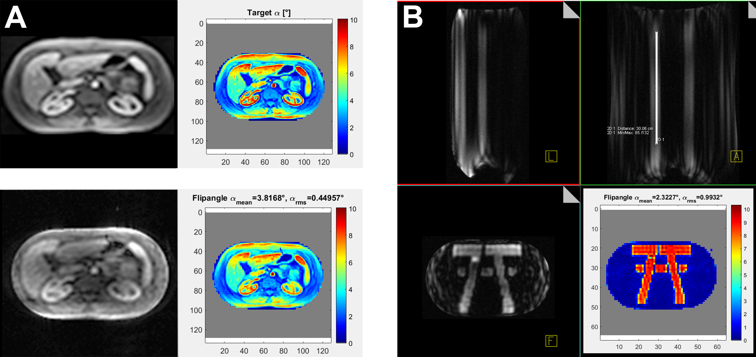
Figure 1 A: 1.5T MR image used as target (left) for pTx pulse calculation
(right). In the lower row: pTx excitation result in oil body phantom (32l;
T1=530ms; T2=300ms; εr=45; σ=0.55S/m; 340x207x500mm3) (left) and result of Bloch simulation (5.36ms pulse duration) (right).
B: ‘7T’ excited within the oil body phantom. Coronal and sagittal view (50cm FOV in z-direction) showing the stability of the excitation calculated based on one central slice. The white line in the upper right image represents a length of 30cm within the phantom. In the lower corner the Bloch simulation of the 5.36ms pTx pulse is shown.
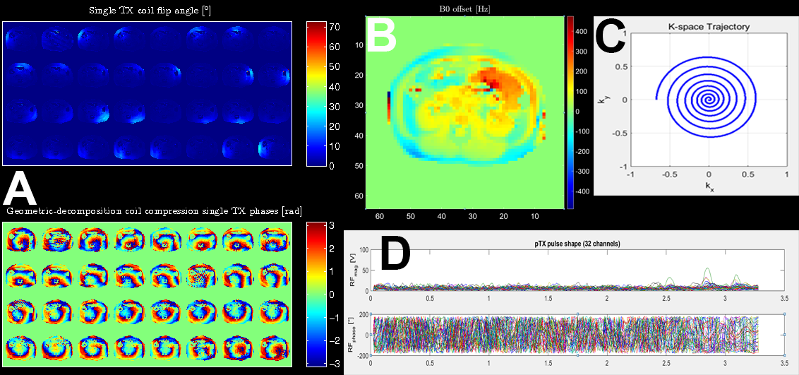
Figure 2 A: 32-channel absolute B1 mapping with phases. B1 maps acquired in intervertebral disc between L2 and L3. (2D, matrix 64x64, performed within breath hold, TE1 = 3.06 ms, TE2 = 4.08 ms, 42 s acquisition time, geometric-decomposition coil compression applied for phase maps). Corresponding B0 map is shown in B. Spiral gradient trajectory with variable density used for 2D pTx pulses (C). D shows the final 32-channel pTx pulse used for the in-vivo measurements.
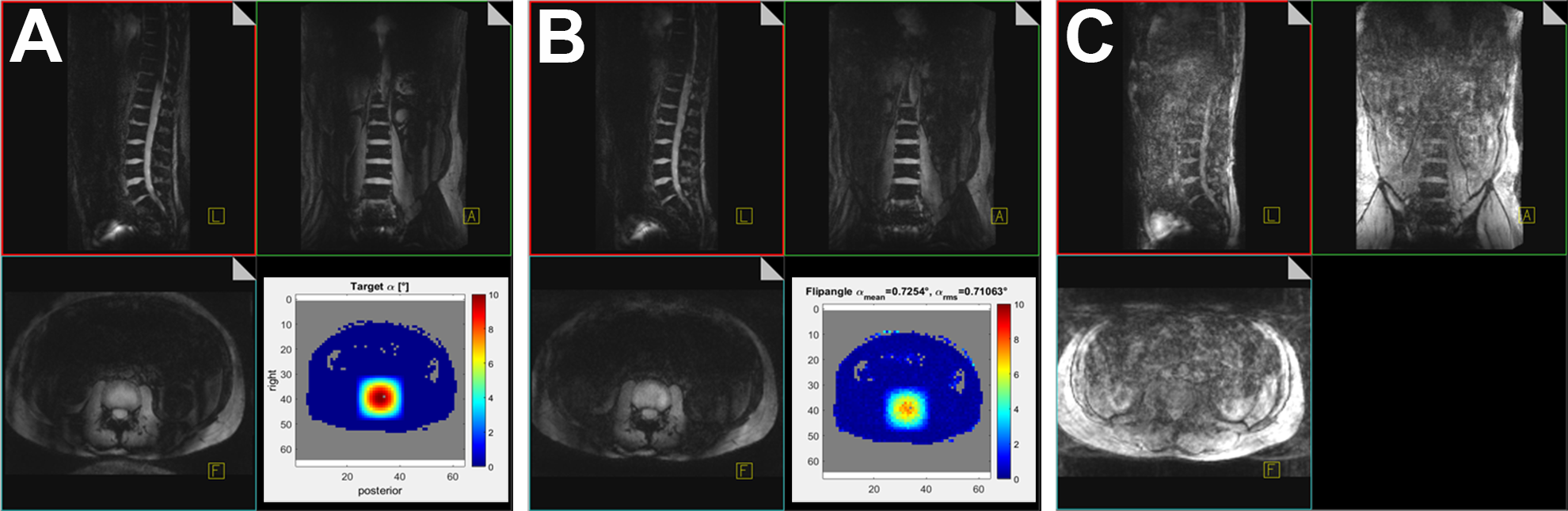
Figure 3 A: pTx during breath hold (TA 1:03; 3D; TE 6ms; TR 12 ms; 120 slices; matrix 168x256; voxel (2mm)3; 240mm x 328mm x 500mm FOV; iPAT 2x2; axial excitation, coronal readout).
B: Same sequence parameters, but acquisition during free breathing. The square root of a Hanning filtered square was used as a target (lower corner of A, Bloch simulation in B).
C: Effects of free breathing in a TIAMO GRE sequence (TA 1:11; 3D; TE 5ms; TR 9ms; 120 slices; matrix 168x256; voxel (2mm)3; 240mm x 328mm x 500mm FOV; iPAT 2x2).
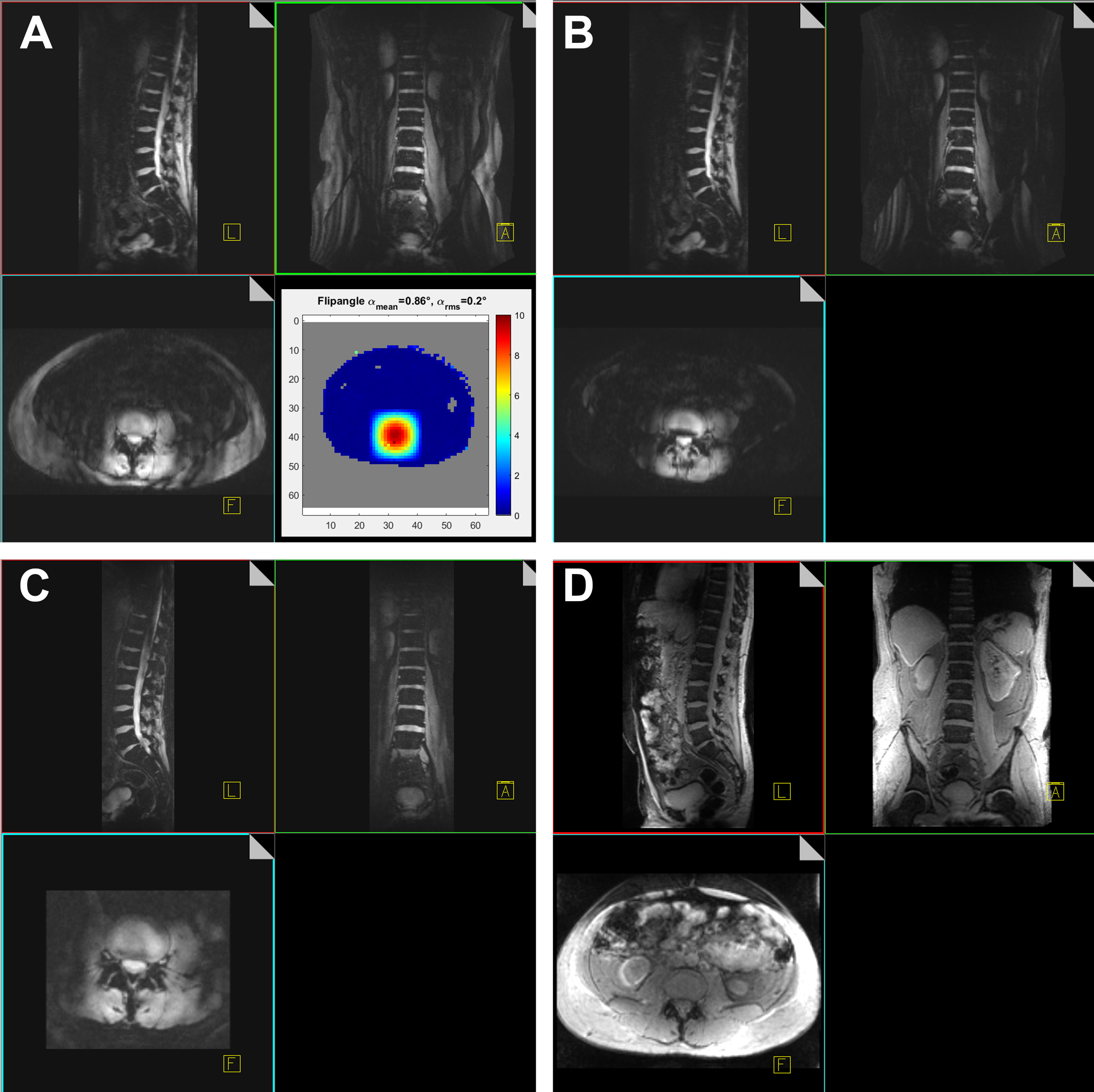
Figure 4 A: pTx excitation using the square root of a Hanning filtered square as target (TA 1:28; 3D; TE/TR 6/20ms; 72 slices; 3mm slice thickness; matrix 192x256; (2mm)2 resolution; 216x375x500mm3 FOV; iPAT 2x2; axial excitation, coronal readout).
B: Same pTx excitation, applying fat suppression (changes: TA 1:37; TR 22ms).
C: Same pTx excitation, fat suppression, reduced FOV (TA 5:18; 2 averages; 88 slices; matrix 104x334; (1.5mm)3 resolution; 132x156x500mm3 FOV; no iPAT).
A-C performed during free breathing.
D: Comparison TIAMO GRE during breath hold (TA 0:48; 3D; TE/TR 3/6ms; 120 slices; matrix 168x256; (2mm)3 resolution; 122x328x500mm3 FOV; iPAT 2x2).