4302
ANALYTICAL RF COILS DECOUPLING: A THEORETICAL APPROACH FOR PARALLEL TRANSMISSION1Department of Life, Health and Environmental Sciences, L'Aquila University, L'Aquila, Italy, 2Laboratori Nazionali del Gran Sasso, Istituto Nazionale di Fisica Nucleare, L'Aquila, Italy, 3Istituto SPIN-CNR, CNR, L'Aquila, Italy, 4Imaging Technology Abruzzo, L'Aquila, Italy
Synopsis
We show, by Finite Elements Modelling, the tuning and matching feasibility of a highly coupled parallel transmission (PTx) array by means of two degrees of freedom (two capacitances values) and decouple them a posteriori. This approach could be useful to simplify the design of PTx arrays avoiding complex procedures to geometrically and/or electrically decouple the elements. The procedure is stable for small parameters changes and this suggests a possible experimental verification of the results.
INTRODUCTION
In the past years parallel transmission (PTx) for MRI1 with arrays of simultaneously operated coils has shown a remarkable development, since PTx can improve RF excitation and eliminate B1 inhomogeneities at high fields2. In the standard approach the transmit elements are decoupled either geometrically and/or electrically3-5. We illustrate, by finite elements simulations, that it is possible to have an 8-channel PTx system with arbitrary couplings between the elements but still capable to have all elements matched and tuned at the desired frequency and to be controlled independently.METHODS
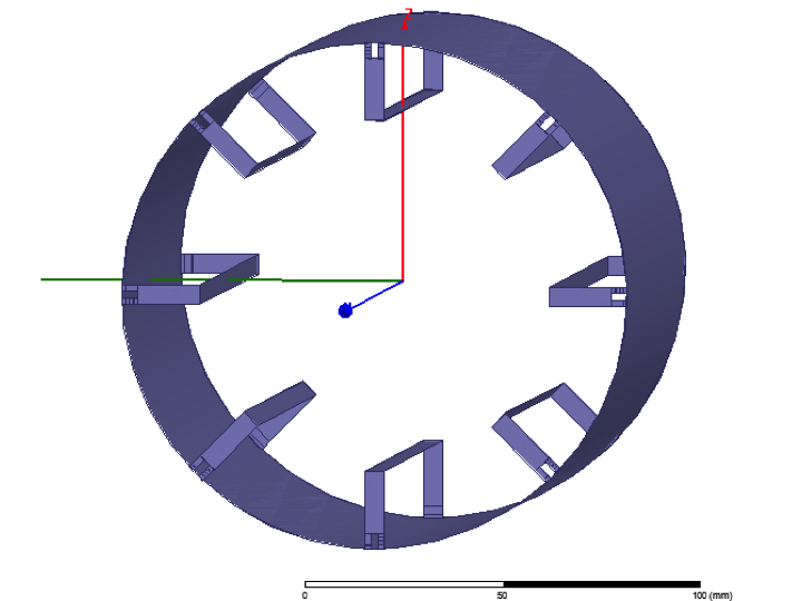
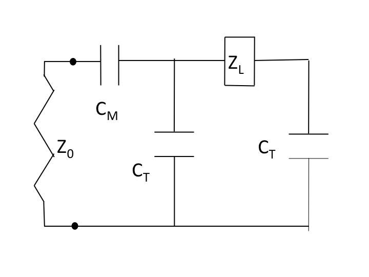
We have designed an 8-channel PTx array for mice/rat applications at f0=100 MHz (Fig. 1). The coil array is 15 cm long, the diameter of the external ground cylinder is 13 cm, the free bore diameter is 9 cm, the legs width is 5 mm and all copper elements are 35 um thick. The elements are disposed like in an 8-legs TEM coil with the legs extremities connected to the ground shield by two tuning capacitors (equal to CT for all the channels). For each coil a single matching capacitor (equal to CM for all the channels) and a Tx port with impedance Z0=50Ω are also present. The electrical scheme of a single channel is reported in Fig. 2 where ZL is the 8x8 complex impedance matrix that accounts for the legs impedance and their mutual coupling. Finite Elements Method (FEM) simulations have been performed using the software HFSS 17.0 (Ansys) on a 2GHz 16 cores PC using the Fast Sweep modality. The calculations related to the lumped parameters model have been performed with MATLAB (Mathworks).RESULTS
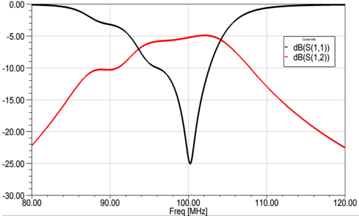
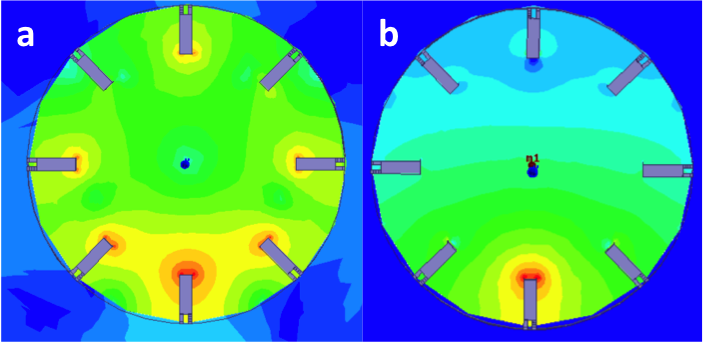
A FEM simulation was used to extract the ZL matrix at the working frequency f0. The lumped parameters model of Fig. 2 is used to extract: (i) the (8x8) impedance matrix of the system Z=ZM+ZT-ZT(ZL+2ZT)-1, where ZM,T are diagonal matrices with non zero entries equal to 1/(ω0CM,T); and (ii) the dependence of the scattering matrix S as a function of CM,T. A minimization code was used to find the target values for the desired 100 MHz working frequency: CT=37.4 pF, CM = 20.0 pF. These elements have been inserted in the FEM model to check the PTx array. Figure 3 shows, for the target values of the capacitors, the simulated diagonal element S11 corresponding to all the ports matched to 50Ω. Figure 3 shows also S12, the coupling coefficient with the next neighbour elements, equal to -5 dB at f0, well above the standard values of PTx arrays. The large coupling is clearly visible if an RF signal is delivered to one port only: currents are excited in all the legs, with different intensities and phases, and the resulting magnetic field inside the array is heavily distorted with respect to the one generated by the isolated element (Fig. 4a). The network scattering theory allows decoupling of the array elements by a linear transformation. The relation between the 8-component excitations vector V and the corresponding currents vector I in the legs is V/I=ZM+ZT-ZT(ZL+2ZT)-1ZT. This relation can be inverted to define the excitation profile that generates a given (arbitrary) current pattern in the legs, hence a given field profile inside the RF coil. As an example Fig. 4b shows the FEM result for the PTx excitation profile calculated as such to excite the lower leg only. This profile is very close to the one observed when a coil composed by one leg only is excited.DISCUSSION
We checked that the results are stable if small (few %) variations of the CM,T values among the different channels are introduced. The FEM simulation introduces numerical errors (of the order of 5%) and this is evident when extracting ZL and S which are not exactly circulant Toeplitz matrices, as it should be expected from the geometrical symmetry of the coil array. The numerical stability of the results can be interpreted as a non-singular behaviour of the matrix that relates the V and I vectors and make us confident that an experimental verification of the simulations is feasible. The presence of a homogenous cylindrical load of saline solution has been considered too in the model. The FEM shows that the small changes in the ZL matrix do not spoil the results.CONCLUSIONS
We have shown that it is possible to tune and match an 8-channel PTx array with two degrees of freedom only and decouple them with a posteriori analytical technique. This approach could be useful to simplify the design of PTx arrays avoiding complex procedures to electrically decouple the elements.Acknowledgements
We thank the Italian Ministry for Economic Development (MISE) for financial support under Grant n. AQ/0009/01-02/X23.References
1. Sotgiu A, Hyde JS, High-order coils as transmitters for NMR imaging. Magn Reson. Med. 1986;3:55–62.
2. Katscher U, Bonert P, Parallel RF transmission in MRI, J. of Magn. Res. Imag. 2012;19:36:55–72.
3. Avdievich N., Pan J.W., Heterington H.P., Resonant inductive decoupling (RID) for transceiver arrays to compensate for both reactive and resistive components of the mutual impedance, NMR in Biomed. 2013;26:1547-1554.
4. Abuelhaija A., Orzada S., Solbach K., Parasitic Element Based Decoupling of 7 Tesla MRI Coil Array, Loughborough Antennas & Propagation Conference 2015.
5. Connell I.R.O., Gilbert K.M., Abou-Khousa M.A., Menon R. S., MRI RF Array Decoupling Method With Magnetic Wall Distributed Filters. IEEE Trans. On Medical Imag., 2015;34:825-835.
Figures