4299
Practical aspects of preamplifier designs for 13C imaging.1Department of Electrical Engineering, Technical University of Denmark, Kgs. Lyngby, Denmark
Synopsis
This abstract presents two preamplifier designs for 13C imaging optimized either for single or array coil usage. For single coil usage the preamplifier is designed to minimize noise yielding a noise figure of 0.25 dB. For array coils coupling between elements is a problem when the input impedance of the preamplifier is high. Hence the main contribution of this work is a low resistance, inductive input impedance preamplifier yielding better decoupling for array coils, while maintaining acceptable gain (20 dB) and noise figure (0.75 dB).
Purpose
Non-magnetic preamplifiers for 3T 13C MRI is a sparse commodity that is, to the authors knowledge, only available from one vendor, WanTcom 1. This abstract presents two 3T 13C MRI preamplifier designs operating at 32.1 MHz. Design 1 is optimized for the noise figure (NF) and intended for single coil usage. Design 2 optimizes input impedance for array coils using preamplifier decoupling 2 which is especially useful when utilizing hyperpolarization 3. Further, this work elaborates on the practical aspects of preamplifier design describing the vital aspects for matching, stability, NF and gain.Methods
The important aspect in designing a preamplifier is choosing a proper device for amplifier realization. For practical considerations, in order to simplify the voltage supply, a positive controlled bias transistor is preferable. This leaves two options: either a bipolar or enhancement mode field effect transistor (FET). Bipolar transistors suffer from an inherently higher 1/f-noise which impairs the achievable noise for a 13C preamplifier. Among FETs an enhancement mode pseudomorphic high electron mobility transistor (pHEMT) from Avago (ATF54143 4) has low NF and is chosen in this work.
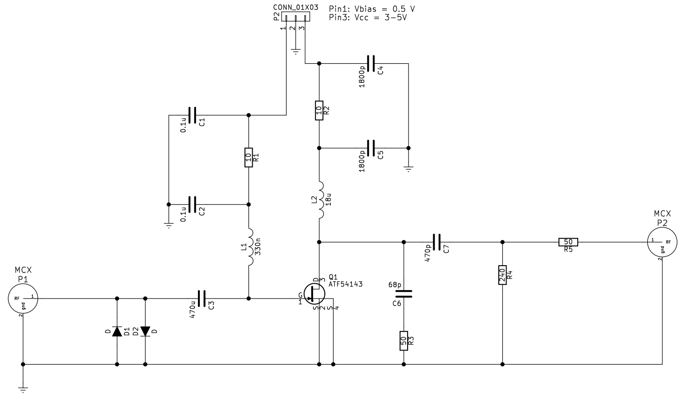
Another important aspect is to determine an unconditionally stable topology. These considerations have led to the common-source topology shown in Fig. 1. A common-gate topology was investigated as well, but was extremely difficult to stabilize. Source degeneration (adding an inductor between source and ground of the transistor) was attempted but showed instability and was discarded.
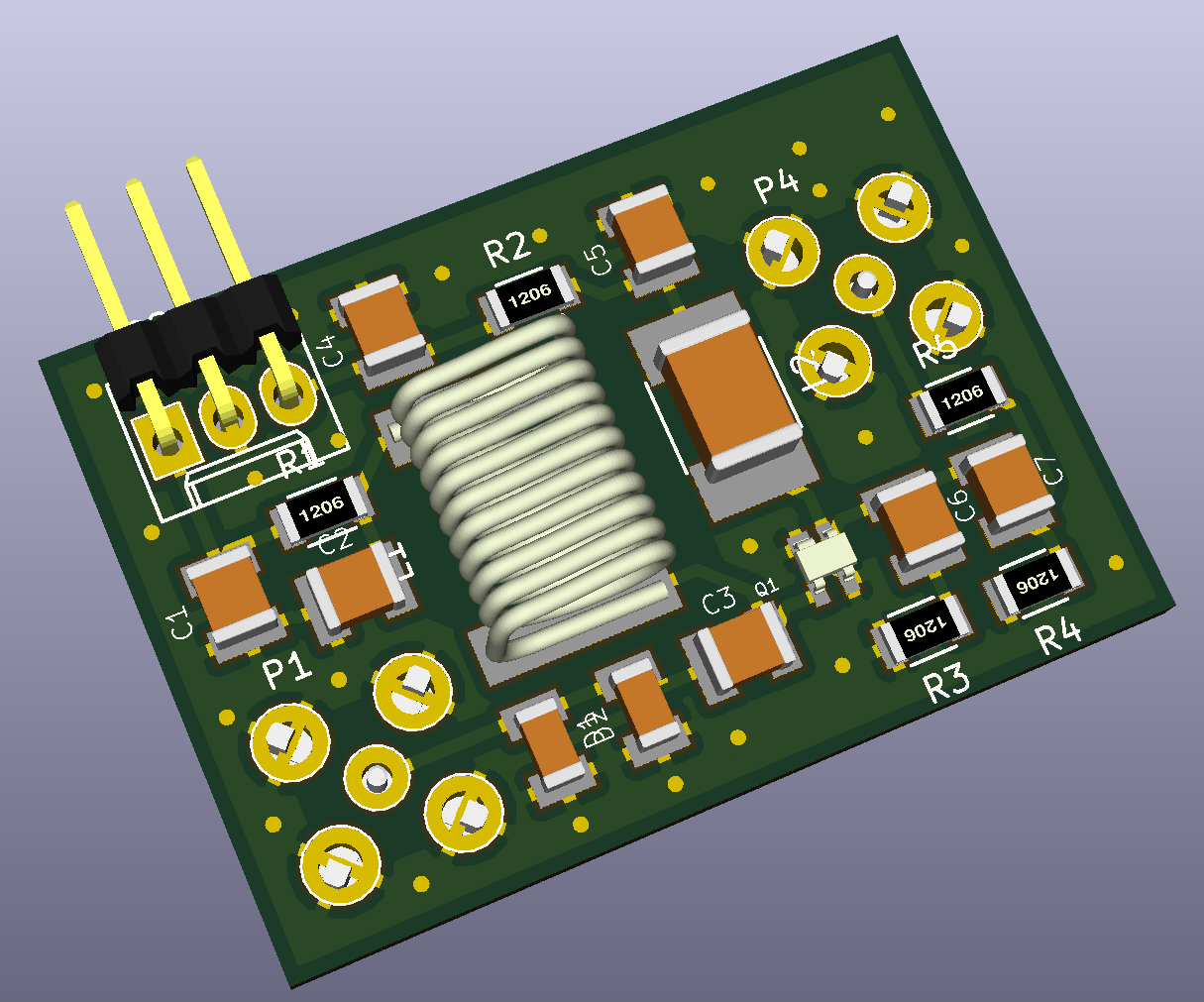
In order to optimize the NF a variable series and shunt 1.5-40 pF capacitor was added externally and tuned for optimal noise performance. The optimal impedance preamplifier is designed for a low resistance and inductive input impedance. The schematic for the optimal impedance design is seen in Fig. 1. C3 is a DC block ensuring that the high input impedance of the transistor is shunted by L1. Hence L1 transforms the high input impedance transistor into a low resistance, inductive preamplifier. The layout for the optimal impedance design is found in Fig. 2.
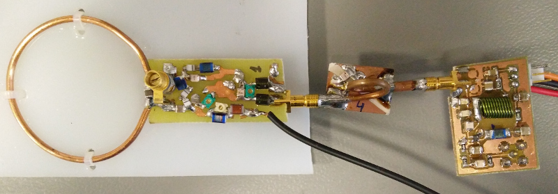
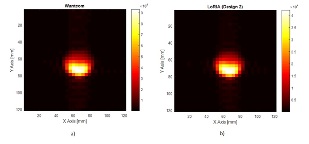
The optimal impedance design and WanTcom WMA32C have been equipped with identical loop coils and measured in a GE Signa HDx 3T clinical scanner 5. Fig. 3 shows the single coil setup with decoupling network and the optimal impedance preamplifier. The imaging sequence was a CSI with an FOV of 120x120x50 mm3, duration of 19 s and 16x16 points, and the phantom was a 1 M 13C-bicarbonate phantom.
Results
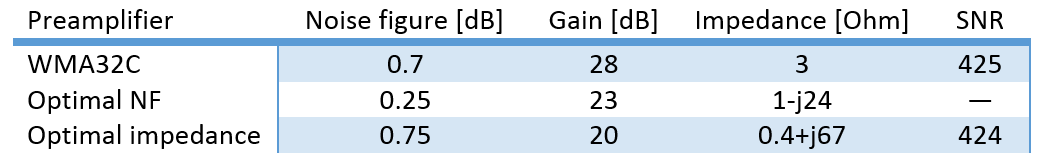
The measured NF, gain and input impedance is found in Table 1 for both designs and the WMA32C. Measured SNR is seen in Fig. 4. Notice that in design 2 the gain drops by 8 dB and NF rises 0.05 dB compared to the WMA32C. However, measured SNR remains unimpaired. In terms of performance of the optimized impedance design in an array please refer to another ISMRM abstract by J. D. Sanchez-Heredia et al.Discussion
The results indicate that preamplifier noise is not the dominant noise contribution for a loop coil of 5 cm diameter. This makes it possible to optimize the preamplifiers impedance yielding better array decoupling while not impairing the single coil’s SNR by trading-off gain and NF. Indeed the exact trade-off between NF, gain, impedance and SNR is unclear but this abstract indicates that the trade-off made here is acceptable.
In terms of the preamplifier designs it may be possible to select another transistor having better low frequency stability. Due to the transistor gain increasing significantly at lower frequencies extra dampening of gain is required. Perhaps another transistor with a worse NF rating may be better at 32 MHz if the extra stability measures were not needed. Also, the output is not matched to 50 ohms though the dampening circuit formed by R4, R5 and the load does yield a match of 2.2:1 VSWR. Hence better performance can be achieved.
Finally, the size of L1 can cause unwanted coupling between the preamplifiers in an array. Hence shielding of the preamplifier is needed.
Conclusion
Two preamplifier designs have been proposed for 3T 13C imaging optimizing either noise figure or the input impedance. The first design showed a noise figure of 0.25 dB making it, to the knowledge of the authors, best in class. However, when considering hyperpolarized 13C imaging an array is usually preferred. Thus the second design optimized the input impedance to 0.4+j67 Ohms with a NF of 0.75 dB and gain of 20 dB. In another abstract, this has proven to yield a significantly better decoupling and thus higher SNR of an array when compared with the WMA32C preamplifier.Acknowledgements
No acknowledgement found.References
1. WanTcom Inc. WMA32C Datasheet. (2013).
2. Roemer, P. B., Edelstein, W. A. & Hayes, C. E. The NMR Phased Array. 225, 192–225 (1990).
3. Lee, R. F. et al. Advantages of parallel imaging in conjunction with hyperpolarized helium - A new approach to MRI of the lung. Magn. Reson. Med. 55, 1132–1141 (2006).
4. Avago. ATF-54143 Datasheet. (2012).
5. Sánchez-Heredia, J. D., Hansen, E. S. S., Laustsen, C., Zhurbenko, V. & Ardenkjaer-Larsen, J. H. Decoupling Scheme for a Cryogenic Rx-Only RF Coil for 13C Imaging at 3T. Proc. Intl. Soc. Mag. Reson. Med. 3639 (2016).
Figures