4297
Wireless Q-spoiling of Receive Coils at 1.5T MRI1Electrical Engineering, Stanford University, Stanford, CA, United States, 2Advanced Coils, GE Healthcare Inc, Aurora, OH, United States
Synopsis
In this work, we demonstrate wireless Q-spoiling of an MRI surface coil in a 1.5T scan using commercial Linx LR series modules. These modules send a digital data stream wirelessly using an On-Off-Keying (OOK) protocol and a carrier frequency of 418MHz. With the simple Linx modules for wireless scanner state detection, it becomes possible to perform tasks such as wirelessly Q-spoiling MRI receive coils and beginning readout of receive coil data. Such steps are necessary for the ultimate goal of wireless MRI.
Introduction
In the grand scheme of making MRI receive coils wireless, there must be a way for the coils to wirelessly detect the scanner state (ie receive or transmit mode) to activate or deactivate Q-spoiling or trigger the receiver electronics to begin readout of free induction decay information. Ideally, this scanner state detection should be performed with minimal access to inner hardware of the MRI system. Solutions from past works include using wireless probes to detect the transmit field [1] or commercial Linx modules that wirelessly transmit digital pulses.
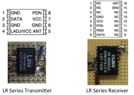
The voltage at the scanner port changes between a positive and negative voltage depending on scanner state. This work uses Linx LR series modules (Figure 1) to transmit scanner state information from the scanner port to a Linx Rx chip on the receive loop for the specific application of Q-spoiling. The receive coils have low power FET based Q-spoiling circuits built on [2]. A switch will be wirelessly activated to detune the coils during transmit mode.
Materials and Methods
A 10.8cm by 14.5cm coil with a GaN HEMT Q-spoiling circuit [2] was constructed and tuned to w0=63.88 MHz (1.5T). The GaN HEMT device is a 75W part from Wolfspeed. To avoid magnetic packaging, we acquired the HEMT in die form and gold wire bonded it to a PCB board.
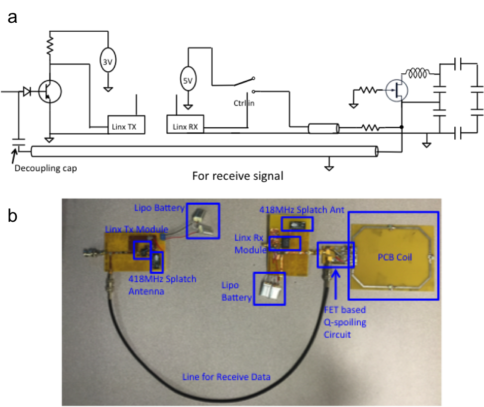
We created a schottky diode-BJT circuit to convert the PIN diode current bias to a voltage bias at the scanner port (Figure 2). The output trigger signal was sent to the input of a Linx LR transmit module which transmitted the control signal across to a Linx LR receive module. This receive module then activated a single-pole double-throw switch, that connected a 5V regulator output to bias on/off the FET Q-spoiling circuit on the MRI receive coil. Splatch antennas made for 418MHz, the carrier frequency of the Linx modules, were used for the transmit and receive LR modules.
A separate coaxial line took the free induction decay signal from the MRI receive coil back to the scanner. We placed a decoupling capacitor near the scanner port between the port and the coaxial line. This blocked the Q-spoil voltage bias signal from transmitting across the coaxial line, ensuring that we achieved wireless Q-spoil gating.
Using an oscilloscope and signal generator, we measured the delay between the rising edge at the scanner port side of our circuit and the resulting falling edge at the end of the Linx receive module chain (see Figure 2a). In addition, we measured the delay between the falling edge at the transmit side and the rising edge at the end of the receive chain.
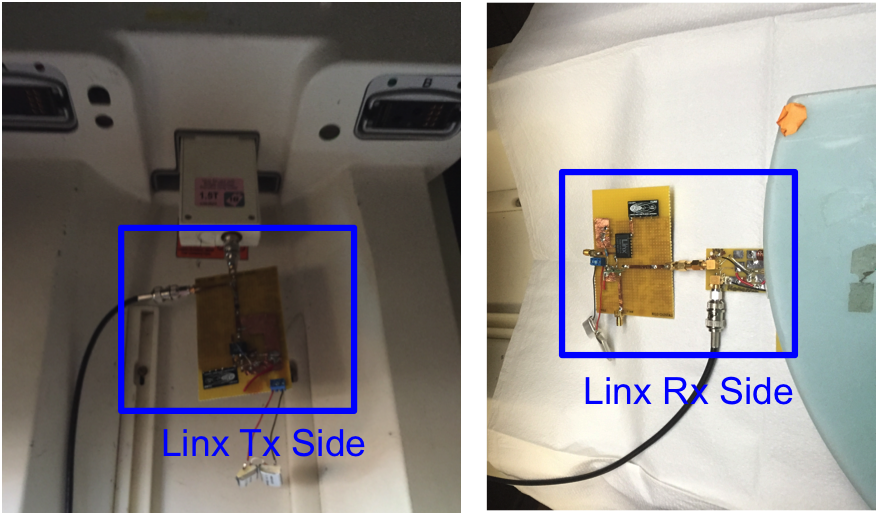
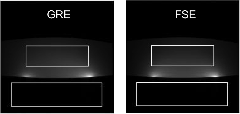
The FET based Q-spoiling coils along with the wireless gating setup were used in a General Electric (GE) 1.5T MRI scanner (Figure 3). Both a typical gradient echo sequence (GRE) (TE=12.6ms, TR=200ms, flip angle=60°, resolution=1.04mmx1.04mm) and fast spin echo sequence (FSE) (TE=20ms, TR=2000ms, echo train=4, resolution=1.04mmx 1.04mm) were performed.
Results
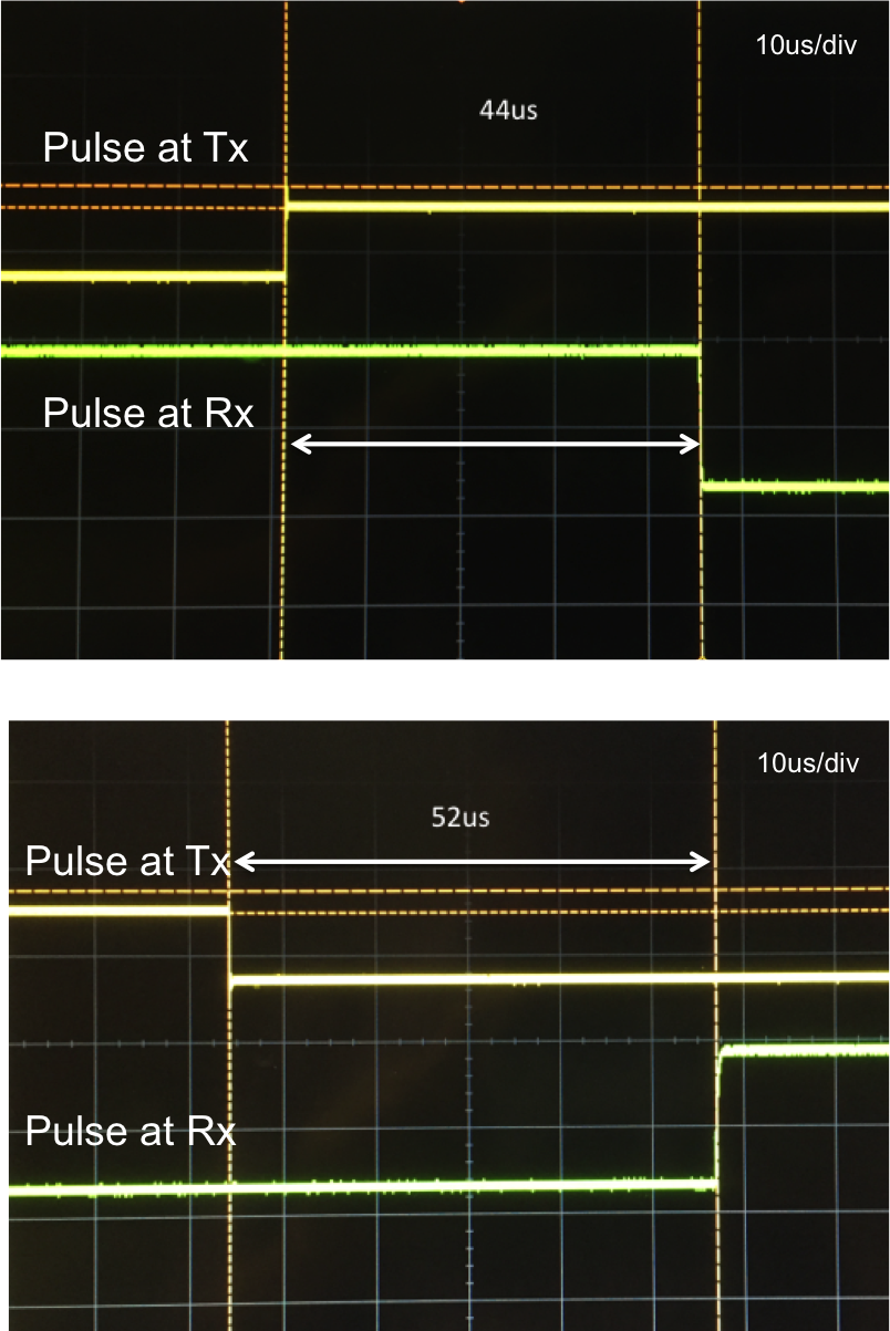
We measured the delay from the rising edge at the scanner port side of our circuit to the resulting falling edge at the output of the receiver Linx module to be 44μs. We measured the delay between a falling edge at the scanner port side to the rising edge at the output to be 52μs. (Figure 4) The latter delay value was short enough to allow the Linx modules to be used for wireless triggering since the delay between the scanner switching to receive mode and the beginning of data readout exceeded 100μs.
We successfully acquired GRE and FSE images. The GRE image had an SNR of 39.8dB, while the FSE image had an SNR of 39.9dB (Figure 5). Artifacts did not seem to appear either from the 418 MHz carrier frequency of the Linx modules nor from Q-spoiling which indicated to us that the setup had performed well.
Discussion and Conclusion
This prototype has an additional safety feature such that if there was a power loss at the Tx side of the linx module, a low level pulse at the Linx Rx end will result in a coil defaulted to Q-spoil mode.
These Linx modules are simple to use for wireless scanner state detection and can easily be applied to other applications such as triggering the start of readout for the electronics in the receive loop, or powering on the LNA in the receive chain in conjunction with Q-spoil activation. It may also be possible to simplify hardware and replace the Linx Rx module with a simple probe to detect the carrier wave transmitted by the Linx Tx module.
Acknowledgements
The authors thank GE, NIH Grant R01EB008108, P01CA15999, R01EB019241, the Stanford Graduate Fellowship and National Science Foundation for funding sources.References
[1] Lu J, Grafendorfer T, Robb F, Pauly J, and Scott G, Wireless Probe Detection For Auxiliary Control Syncing, ISMRM 24, 2180, 2016
[2] Lu J, Grafendorfer T, Zhang T, Vasanawal S, Robb F, Pauly J, Scott G, Depletion-Mode GaN HEMT Q-spoil Switches for MRI Coils, IEEE Transactions on Medical Imaging, Aug 2016
Figures