4295
Decoupling and Integration of Electric Dipoles into RF Arrays1Centre for Functional and Metabolic Mapping, Robarts Research Institute, London, ON, Canada, 2Medical Biophysics, University of Western Ontario, London, ON, Canada
Synopsis
To-date, increasing interest in adapting dipole antennae for imaging at ultra-high field strengths has spawned the design and construction of many dipole-based RF arrays. However, increased electric-field interactions between dipole-to-sample and dipole-to-dipole provide an implementation barrier due to mutual coupling and load-sensitivity. This study presents an analysis of dipole-to-dipole coupling and implements a filter design method to isolate dipole elements in a highly-conformal array designed for human brain imaging at 7 Tesla.
Introduction
Multi-channel radio-frequency (RF) arrays provide individual sensitivity profiles that when used in concert with optimized gradient and RF waveforms can overcome transmission field (B1+) inhomogeneity at ultra-high field (UHF) or reduce specific absorption rate (SAR) via B1+ or RF shimming1. Due to a mixture of near- and far-field electromagnetic interactions occurring at UHF, electric dipole arrays are finding increasing utility at UHF when compared to more conventional RF loop elements2. However, synthesizing dipole arrays presents a technical challenge.
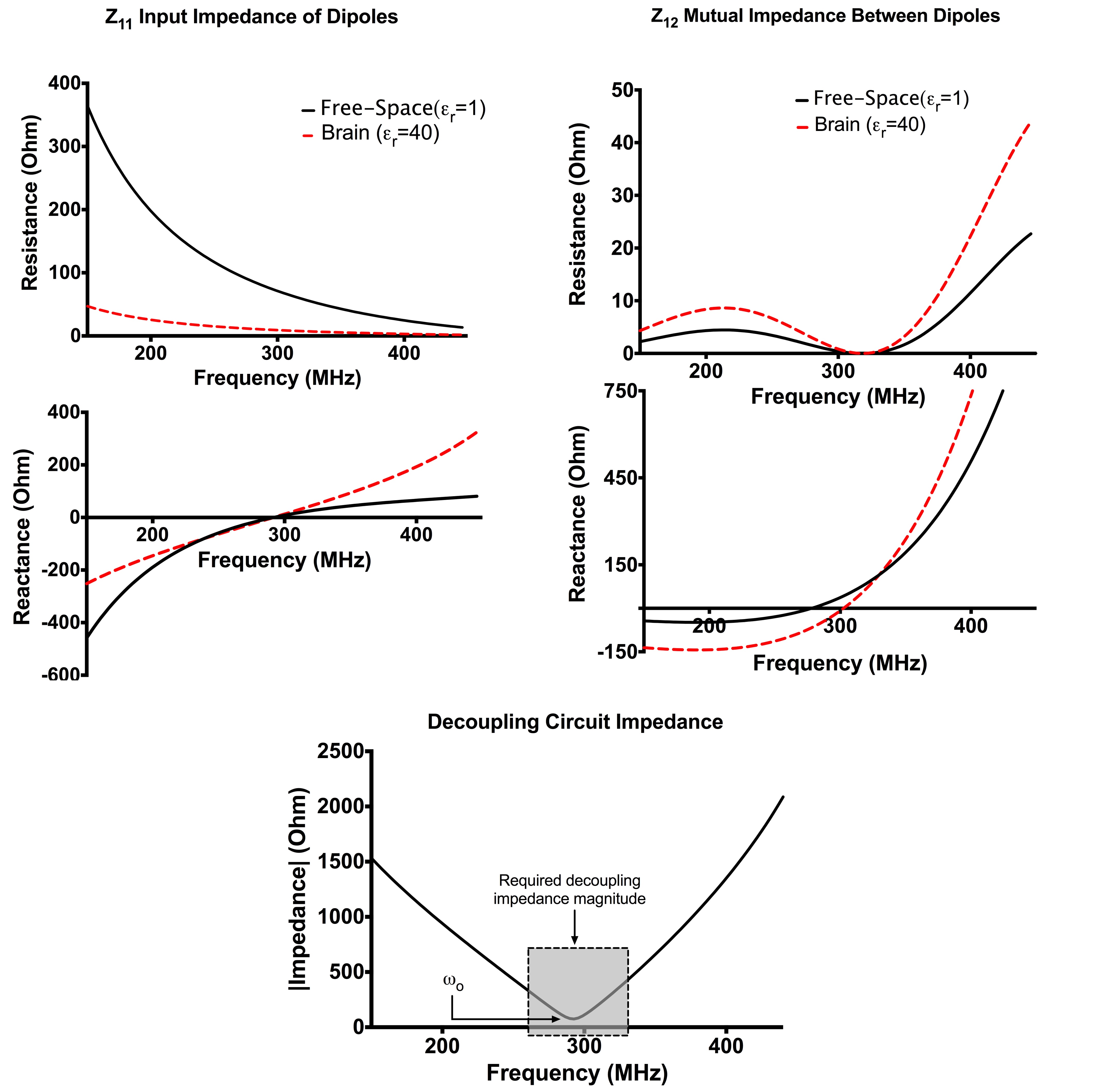
Fig. 1 presents the input impedance (Z11) calculated for a dipole in free space and next to a conducting medium, as well as the mutual impedance (Z12) between two dipoles. As demonstrated in Fig. 1, near resonance the dipole electrically interacts with the sample. This increases the capacitive reactance of the input impedance of the dipole element (Z11 in Fig. 1). Similarly, the capacitive reactance of the mutual impedance between two dipoles (Z12 in Fig. 1) is increased when compared to that of dipoles in free-space. This increased electrical interaction between dipole-to-dipole and dipole-to-sample occurs due to a lossy pathway in a closely-spaced high-permittivity medium. As demonstrated in Fig. 1, decoupling of loaded dipoles is limited by the applicability of conventional decoupling methods for two reasons: (a) increased slope of the mutual reactance near-resonance and (b) increased magnitude of coupling due to both inductive and electric sources. Ideal decoupling impedance, via insertion of an additional ladder section between dipoles, is solved for via computing the eigenmodes of the decoupled array and is presented in Fig. 1 clearly demonstrating the need for a resonant decoupling section.
In this study, mutual coupling is compensated for via a general decoupling solution with ladder filters3. The filters approximate the required decoupling impedance (Fig. 1) between dipole elements. The decoupling method is applied to a transciever array composed of conformal, meandered dipole antennas - array elements that are not easily decoupled by current approaches.
Methods
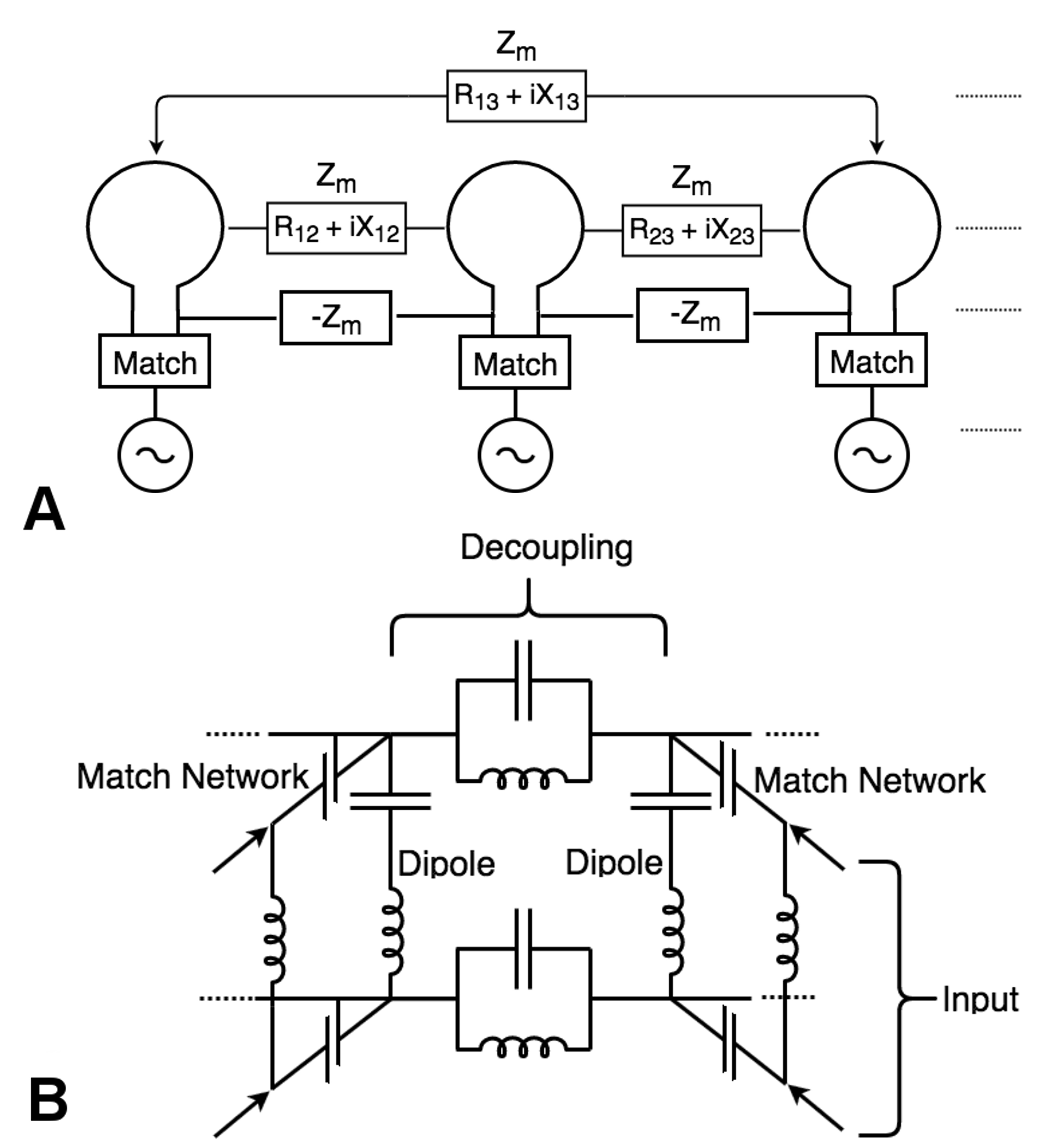
Coupling matrix synthesis (CMS) designs ladder filter networks by fitting prescribed filter responses to analytic polynomials3. A CMS solution has been adapted for implementing a conformal, meandered dipole array designed for human head imaging at 7 Tesla. A building block of the CMS circuit design is presented in Fig. 2a with the specific circuit utilized in this study presented in Fig. 2b. The dipole elements compose the ladder legs of the RF array, with matching networks inserted, transforming the input impedance of the dipole input to power match the complex dielectric load. Additional resonant decoupling circuits complete the band-stop PI network, and the cascaded filter is tiled across to span the entire RF array.
The dipole array was constructed on an elliptical former (minor and major axes: 17 cm and 20.5 m, respectively) and was composed of eight resonant dipoles implemented with 32 mm wide 2 oz. copper traces, routed atop 0.79-mm-thick garolite. Dipoles were matched to 50 (via low-pass PI matching circuits utilizing two variable capacitors (1 – 30 pF, Johanson Manufacturing, NJ) and one variable inductor (25 – 34 nH, Coilcraft, IL, USA). Sleeve baluns were constructed using triaxial cable (double braid shield, 20 AWG, Belden, IN, USA), and were directly fed to the dipole matching circuit from externally mounted BNC connectors.
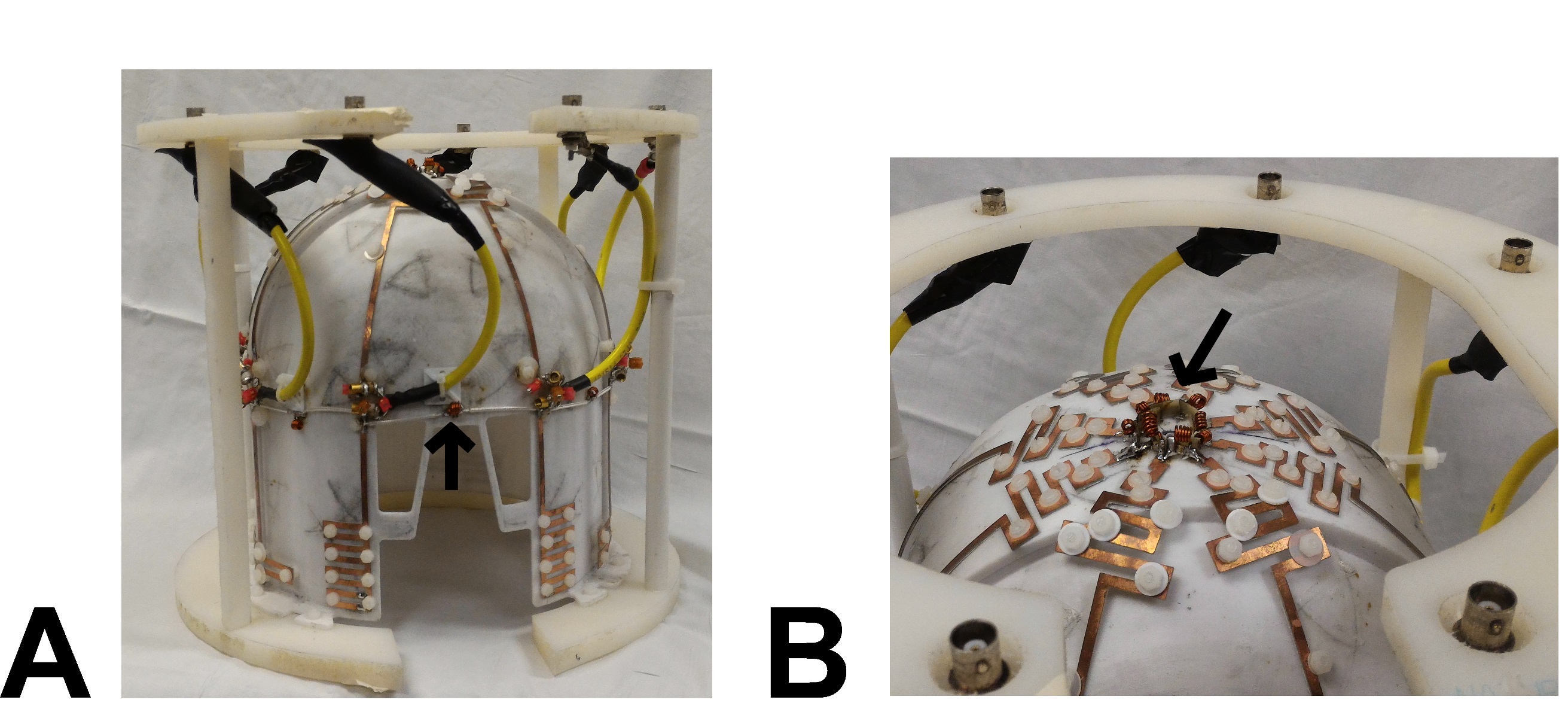
Due to the conformal geometry (see Fig. 3a,b), one half of the balanced form of the decoupling network could be achieved by directly soldering the parallel inductor/capacitor ladder sections between dipoles located at the top of the head (see Fig. 3b). The second half of the decoupling network was connected via coaxial cables between elements (Fig. 3a). The additional capacitive phase shift induced in the decoupling portion of the ladder was compensated for via tuning the parallel inductor/capacitor section.
Results
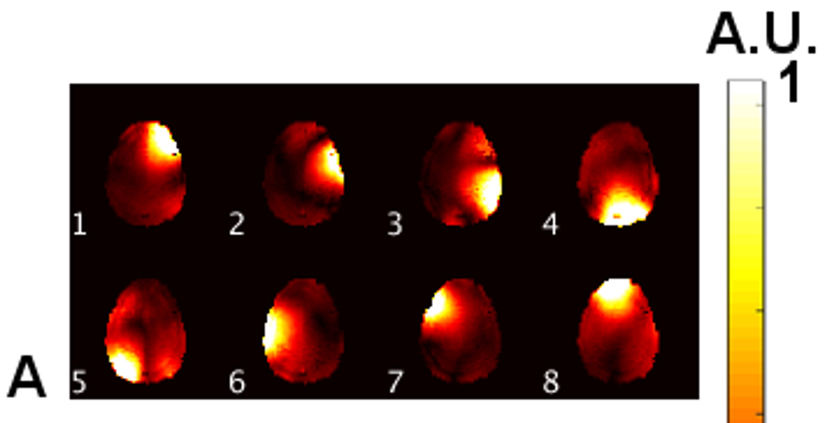
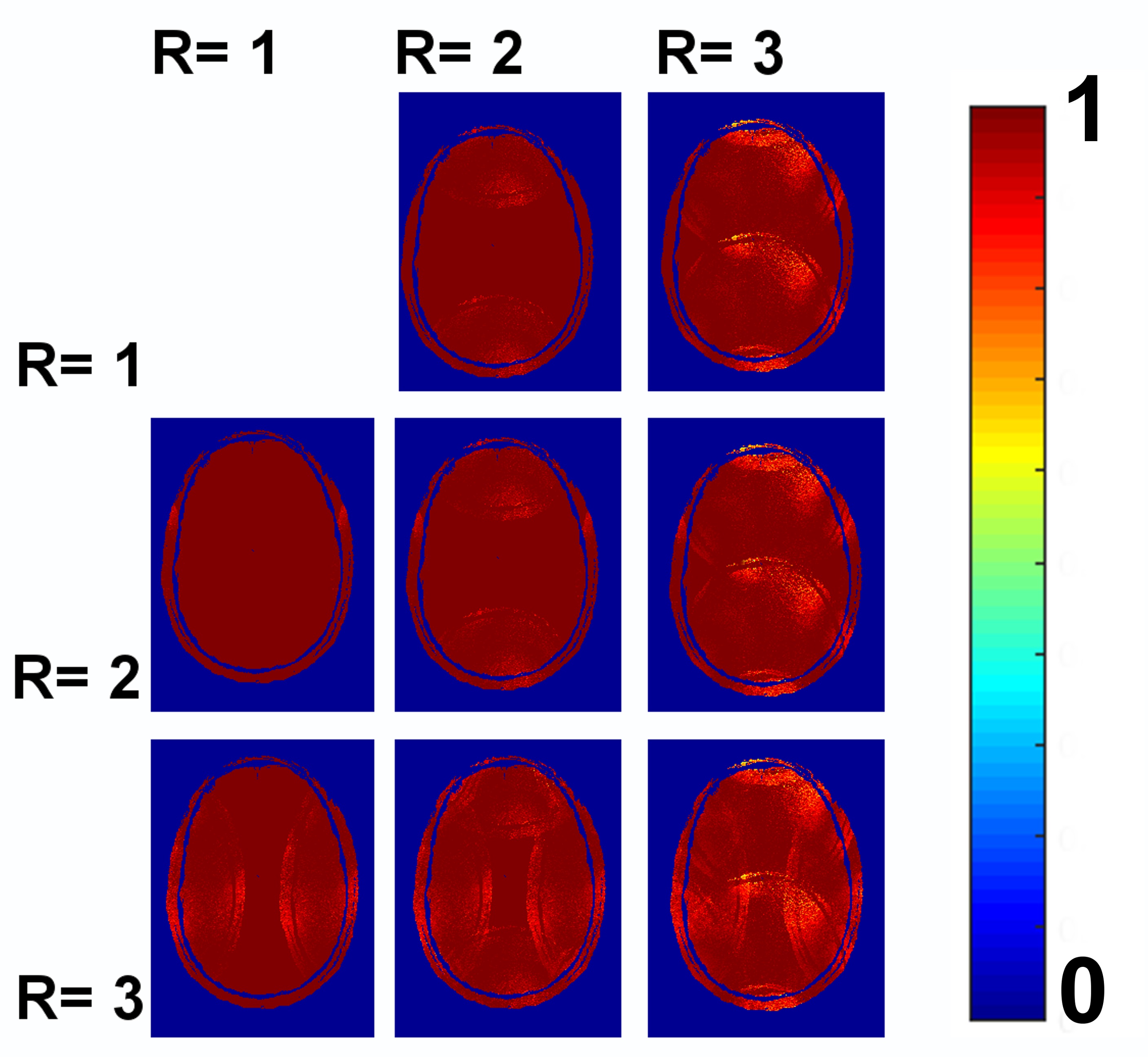
Mean and worst-case transmission between nearest-neighbour dipoles was – 17.2 ± 2.4 dB and –15.5 dB, respectively. Mean transmission across all dipoles was – 22.2 ± 2.4 dB. As seen in Fig. 4, the individual B1+ sensitivity profiles demonstrate that the decoupling method was effective at reducing coupling to a suitable level for routine imaging. Results for up to 3x3-fold acceleration are presented in Fig. 5 with a maximum G-factor of 1.7 measured for 3x3-fold acceleration. More modest acceleration factors of 1x2 and 2x1 resulted in maximum G-factors of 1.2 and 1.1, respectively.Conclusion
In this study the application of coupling matrix synthesis (CMS) for designing RF arrays as a large, multiply terminated RF ladder filter was applied to an unorthodox meandering dipole structure and demonstrated excellent decoupling of an array structure not well-suited for decoupling by conventional methods.Acknowledgements
No acknowledgement found.References
1. Curtis, A. et. al., Slice-by-slice RF Shimming at 7 T. MRM, 2012.
2. Raaijmakers, AJ. et. al., Design of a radiative surface coil array element at 7 T: the single-side adapted dipole antenna. MRM, 2011.
3. Connell, IRO. et. al., General Coupling Matrix Synthesis for Decoupling MRI RF Arrays. IEEE-TMI, 2016.
Figures