4292
New resonator geometries for ICE decoupling of loop arrays1Institute of Imaging Science, Vanderbilt University, Nashville, TN, United States, 2Department of Radiology and Radiological Sciences, Vanderbilt University, Nashville, TN, United States, 3Department of Biomedical Engineering, Vanderbilt University, Nashville, TN, United States
Synopsis
To overcome B1 inhomogeneities and technological difficulties in building large-sized volume resonators, multi-channel arrays are commonly used for transmission at ultra-high fields. One of the main challenges in designing transmit arrays is to minimize the coupling among coil elements. The induced current elimination (ICE) method, which uses additional resonator elements to cancel coils’ mutual electromagnetic (EM) coupling, has proven to be a simple and efficient approach to
Introduction
To overcome B1 inhomogeneities and technological difficulties in building large-sized volume resonators, multi-channel arrays are commonly used for transmission at ultra-high fields. One of the main challenges in designing transmit arrays is to minimize the coupling among coil elements. The induced current elimination (ICE) method1, which uses additional resonator elements to cancel coils’ mutual electromagnetic (EM) coupling, has proven to be a simple and efficient approach to decoupling loop, stripline and dipole arrays1-3. However, in previous embodiments the decoupling elements acted as “magnetic-walls”, blocking the magnetic field and leading to MR signal loss near the elements. In this study, we improved the ICE method to avoid the signal cancellation by using overlapped and perpendicular decoupling loops.Methods
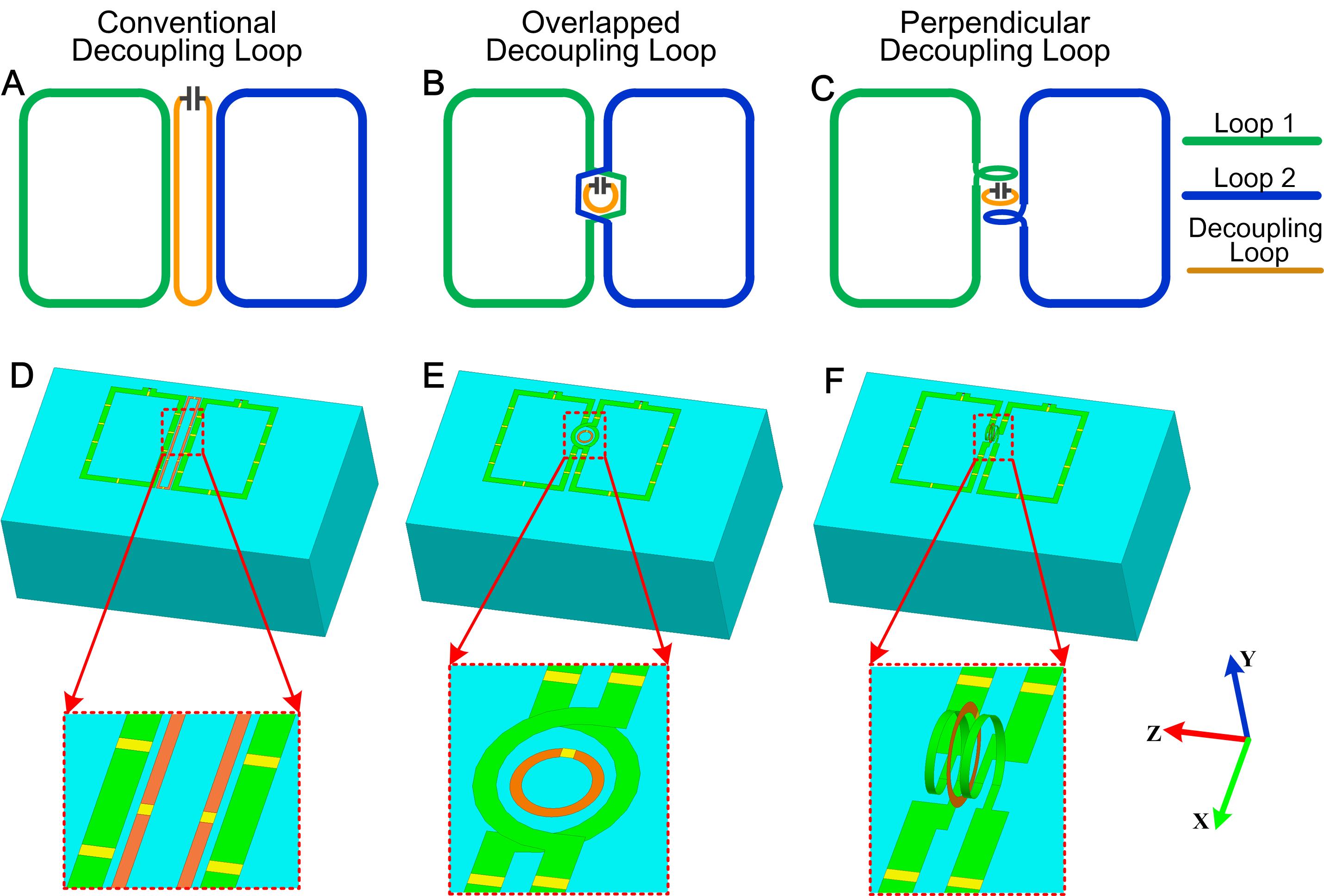
For two identical coils with one ICE decoupling loop between them, the decoupling loop’s current is equal to: $$$I_d=-(Z_{12}⁄Z_{1d}) I=-ηI$$$ when one coil is excited with current $$$I$$$, where $$$Z_{12}$$$ is the mutual impedance between the two coils, and $$$Z_{1d}$$$ is the mutual impedance between the coil and decoupling loop. In previous ICE-decoupled loop arrays (Fig. 1A), $$$η$$$ is positive so that $$$I_d∝-I$$$. Therefore the decoupling loop carries a current in the opposite direction of the coils and acts as a “magnetic-wall” that diminishes the total B1 fields near it, leading to signal loss.
However, if the coils are instead overlapped and the decoupling loop is positioned in the coils’ overlapped area (Fig. 1B), then $$$η$$$ is negative and $$$I_d∝I$$$. Thus the decoupling loop’s current is in the same direction as the coil currents, which may enhance the MR signal near the decoupling loop. If the overlapped conductor segments and the decoupling element are further rotated ninety degrees (Fig. 1C), then the decoupling loop will carry current in a plane perpendicular to the coil currents, and may decouple them without affecting their individual EM fields.
To validate these proposed decoupling geometries, a series of EM simulations were performed with HFSS (ANSYS, Canonsburg, PA, USA). Each array consisted of two planar loops (dimension of 10.5x15 cm2) along the z-direction and a decoupling loop. Figs. 1D, 1E and 1F show simulation models of three arrays with conventional, overlapped and perpendicular decoupling loops, respectively. A water phantom with dimensions 40x25x15 cm3 (б=0.6 S/m and ξr=78) was placed 4cm below each array. All loop elements were matched to 50 ohms and tuned to 298 MHz. The same arrays were then built and validated in bench measurements and MR experiments using a 7T Philips Achieva scanner (Philips Healthcare, Cleveland, Ohio, USA).
Results
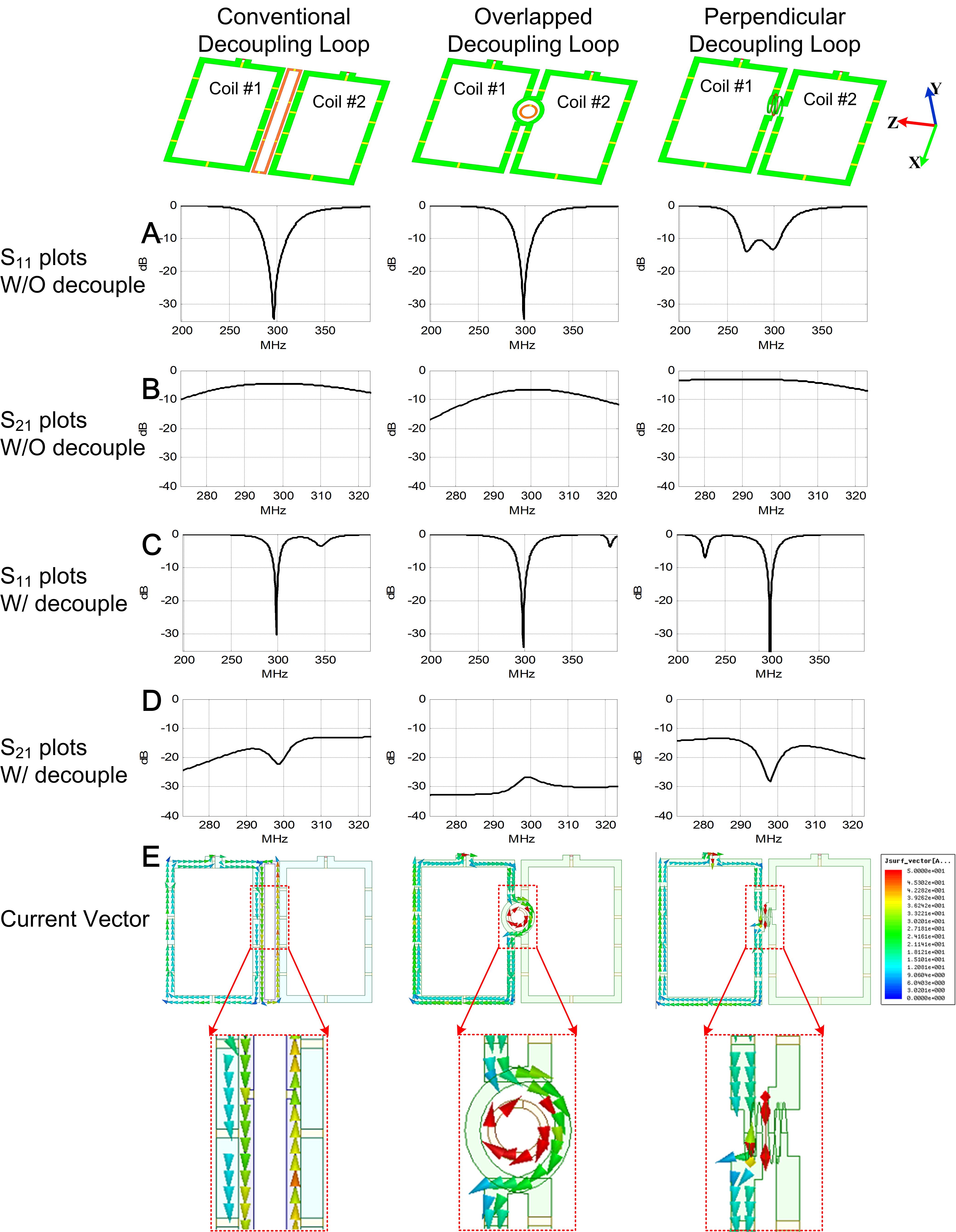
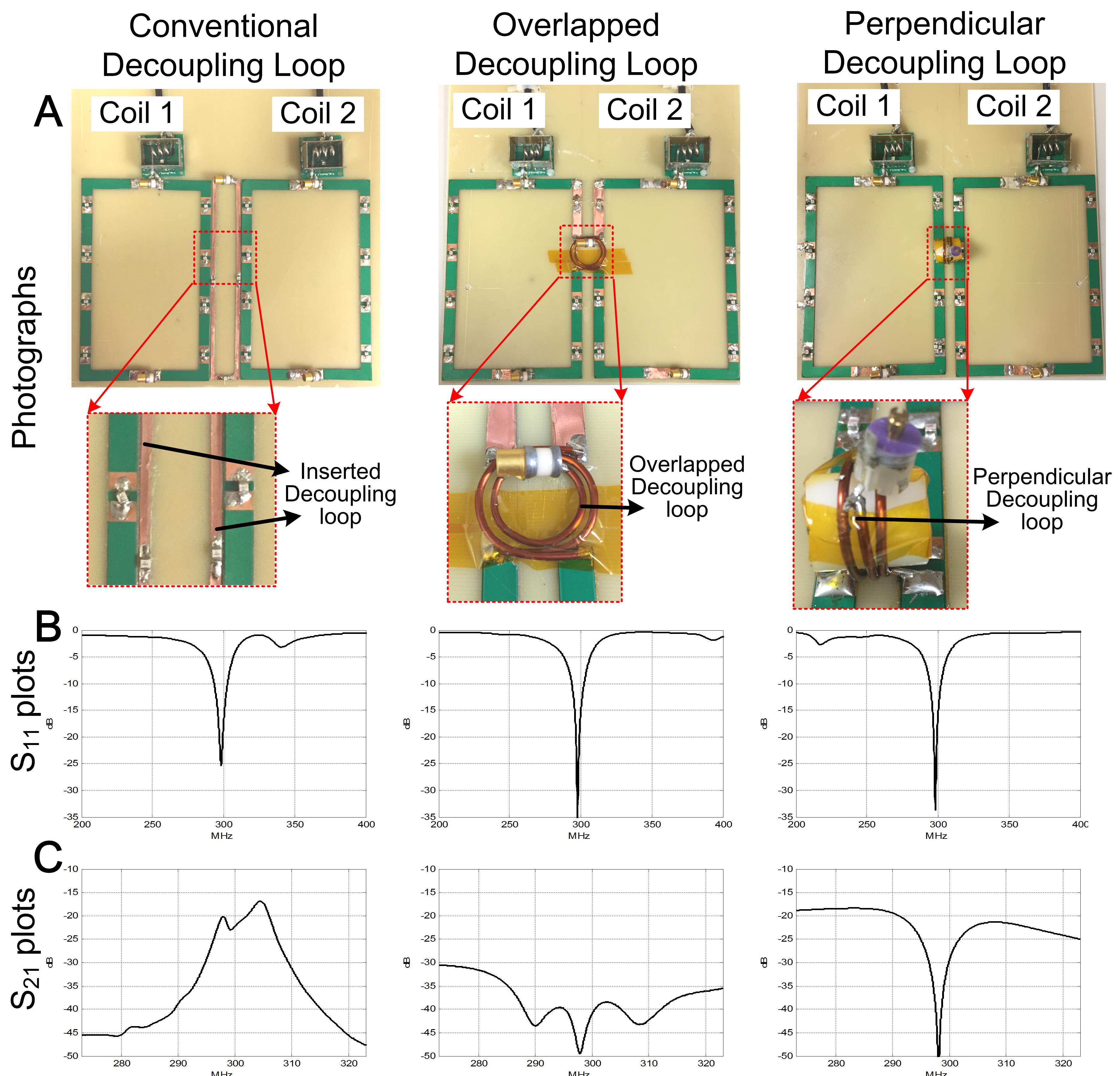
Figs. 2A and 2B show S-parameter plots without decoupling loops. In this case, the coil elements are strong coupled (Fig. 2B, S21=-4.5, -6.6 and -3.2 dB) which leads to resonance peak splitting or asymmetry (Fig. 2A). When decoupling loops were added, the coil elements were well decoupled with S21<-20 dB (Fig. 2D). Fig. 2E shows the current vectors when the left coil was excited. As expected, the current direction of conventional decoupling loop is the opposite (anti-clockwise) while the current direction of overlapped decoupling loop is the same (clockwise) as that of the excited coil (clockwise). Fig. 3A shows photographs of the fabricated arrays. The measured isolations of the three arrays are -22.8, -49.2 and -46.8 dB, respectively (Fig. 3C).
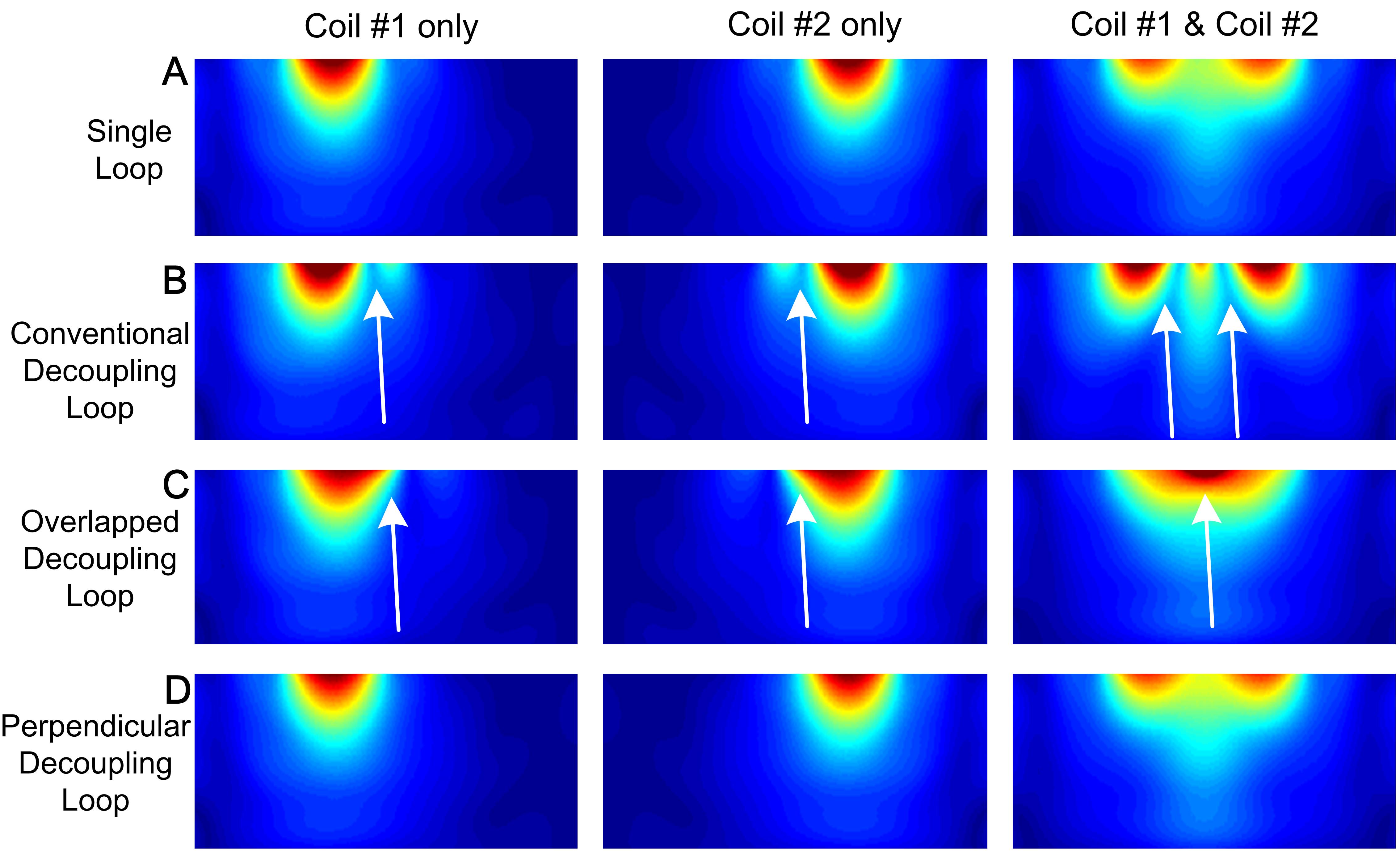
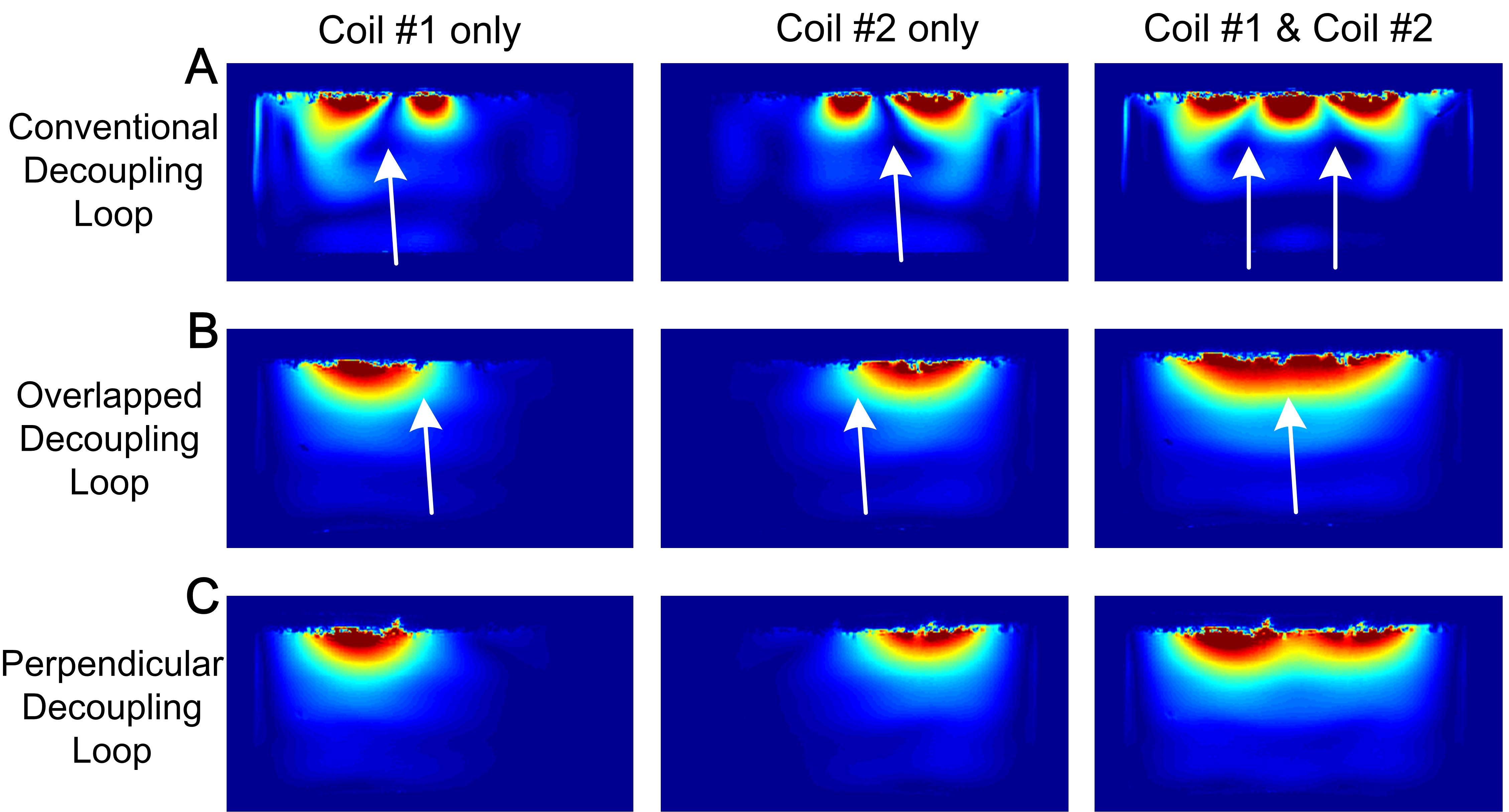
Fig. 4 shows simulated image profiles. The conventional decoupling loop decreased nearby signal (white arrows in Fig. 4B), reflecting its “magnetic wall” behavior. In contrast, the overlapped decoupling loop enhanced nearby signal (white arrows in Fig. 4C), and the perpendicular decoupling loop maintained the signal intensity of the coils driven in isolation (Fig. 4D vs Fig. 4A). Fig. 5 shows experimentally acquired GRE images obtained with these arrays. Similar to the simulation results, the conventional decoupling loop exhibits signal cancelation (Fig. 5A), which is avoided using overlapped (Fig. 5B) and perpendicular decoupling loops (Fig. 5C).
Discussions and Conclusion
The measured isolations of the proposed ICE-decoupled loop arrays (Fig. 3C) were better than -45 dB, indicating that both mutual resistance and reactance were removed4. Improved decoupling loops also have much smaller dimensions (diameter 1.6cm) compared to conventional loops (2.8x15cm2), making them more suitable for compact array designs. In spite of their small dimension, the self-resonance frequencies of the proposed decoupling loops (395 MHz and 212 MHz) were still far away from the Larmor frequency (298 MHz) due to overlapping and transformer effects. In conclusion, we proposed new decoupling geometries for ICE-decoupled loop arrays and validated them in both simulations and experiments. By using the new methods, excellent decoupling performance can be achieved (<-45 dB) without disturbing MR signals near the decoupling elements.Acknowledgements
This work was supported by NIH R01 EB 016695 and NIH R21 EB 018521.References
1. Li Y, Xie Z, Pang Y, et al. "ICE decoupling technique for RF coil array designs," Medical Physics, vol. 38, pp. 4086-4073, 2011.
2. Yan X, Zhang X, Feng B, Ma C, Wei L and Xue R. "7T Transmit/Receive Arrays Using ICE Decoupling for Human Head MR Imaging," in IEEE Transactions on Medical Imaging, vol. 33, no. 9, pp. 1781-1787, Sept. 2014. doi: 10.1109/TMI.2014.2313879.
3. Yan X, Zhang X, Wei L, Xue R. Design and test of magnetic wall decoupling for dipole transmit/receive array for MR imaging at the ultrahigh field of 7T. Appl. Magn. Reson., 46 (1) (2015), pp. 59–66.
4. Avdievich NI, Pan JW, Hetherington HP. Resonant inductive decoupling (RID) for transceiver arrays to compensate for both reactive and resistive components of the mutual impedance. NMR Biomed2013;26:1547-54.
Figures