4290
Ultra-high field RF coils with adjustable longitudinal coverage: Traveling-wave meets standing-wave1Institute of Imaging Science, Vanderbilt University, Nashville, TN, United States, 2Department of Radiology and Radiological Sciences, Vanderbilt University, Nashville, TN, United States, 3Department of Biomedical Engineering, Vanderbilt University, Nashville, TN, United States
Synopsis
7T scanners currently are not equipped with body coils, so for MR imaging of relatively short coverage along the z-direction (head,
Purpose
7T scanners currently are not equipped with body coils, so for MR imaging of relatively short coverage along the z-direction (head, knee and prostate), local transmit coils with standing-wave behavior are commonly used to achieve high efficiency1-3. For MR imaging that requires long coverage such as the legs, traveling wave MRI is potentially a competitive choice since it is extremely simple to implement and enables large FOV imaging4-6. In this study, we propose a coverage-adjustable transmit coil which combines the concepts of traveling-wave and standing-wave. The new design exhibits excellent efficiency over short regions, but maintains the ability to cover longer areas for MR imaging of the legs or whole body.Methods
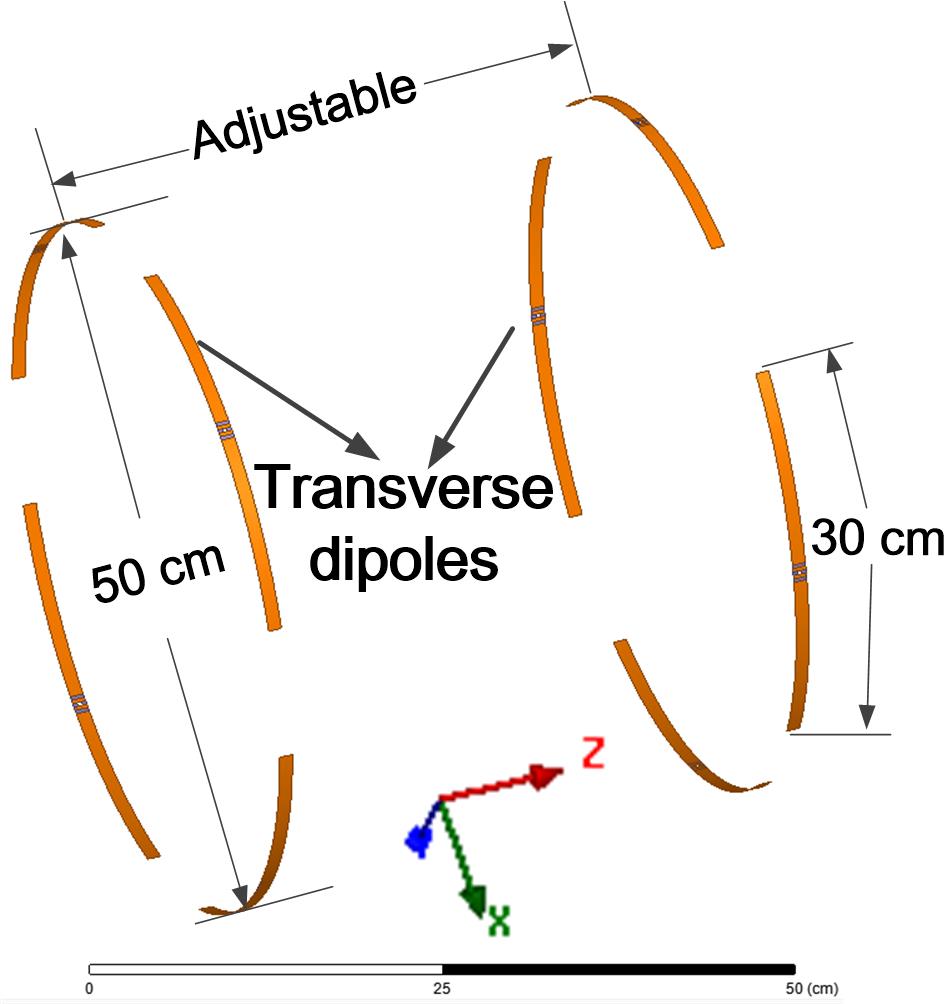
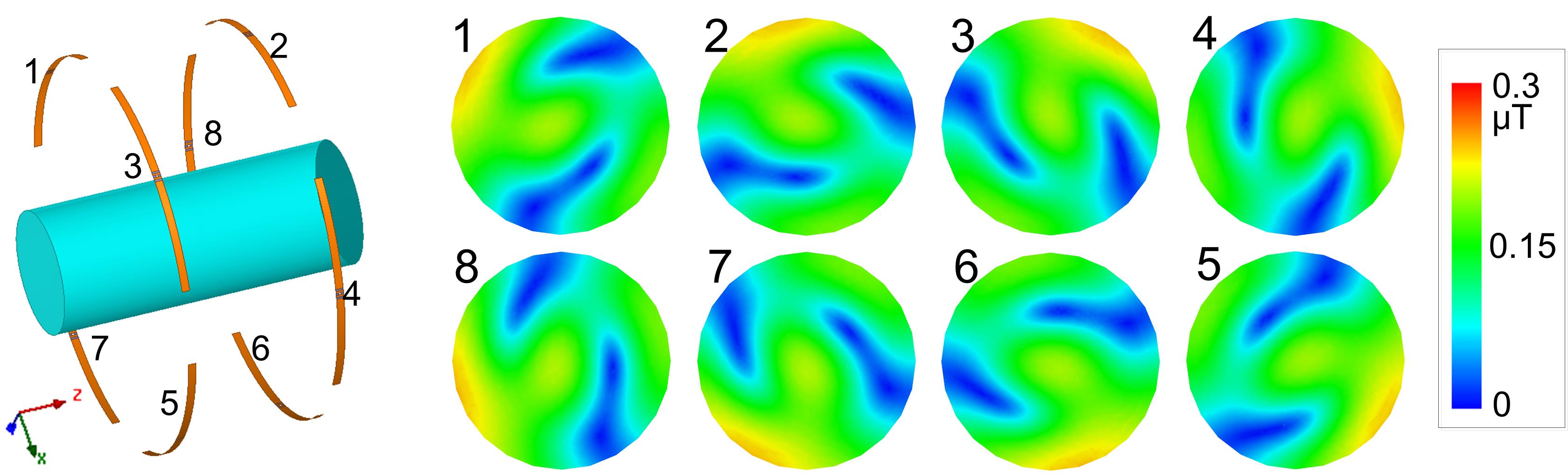
Simulations were performed using HFSS (Ansys, Canonsburg, PA, USA) to explore the new coil performance and compare it with other traditional coils. In all simulations, coil elements were tuned to the Larmor frequency of 7T (298 MHz) and matched to 50 Ω. The new traveling+standing-wave coil comprises two rings (Fig. 1). In each ring, four transverse dipoles (30 cm long and 1 cm wide) are placed head-to-head and driven with sequenced 90-degree phase increments to generate a CP traveling wave field.
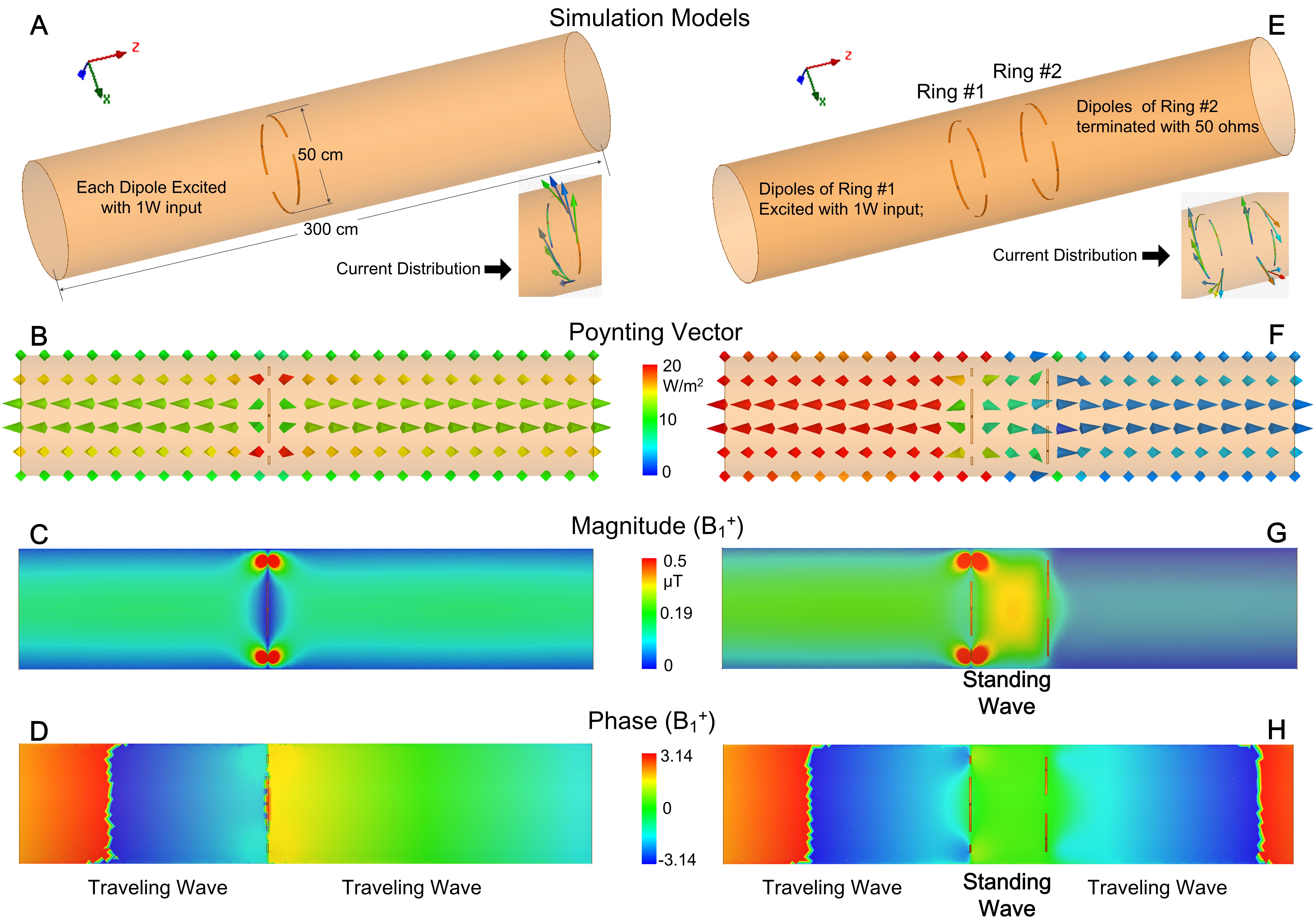
1. Standing-wave region produced by two traveling-wave antennas
A whole-body MRI bore (diameter 60 cm) forms a waveguide at 7T, so transverse dipoles in a single ring (Fig. 2A) demonstrate traveling-wave behavior (Figs. 2B-2D). In the presence of another ring (Fig. 2E), however, a standing-wave region appears (Fig. 2G). This is evidenced by the B1 phase distribution along the z-direction in the region between the two rings, which is uniform rather than linear (Fig. 2H). The B1 amplitude in the standing-wave region is approximately a factor of two higher than with a single ring, and its extent can be easily adjusted by varying the distance between two rings. The enhancement that results from the second ring is analogous to the function of reflectors in a Yagi-Uda antenna7.
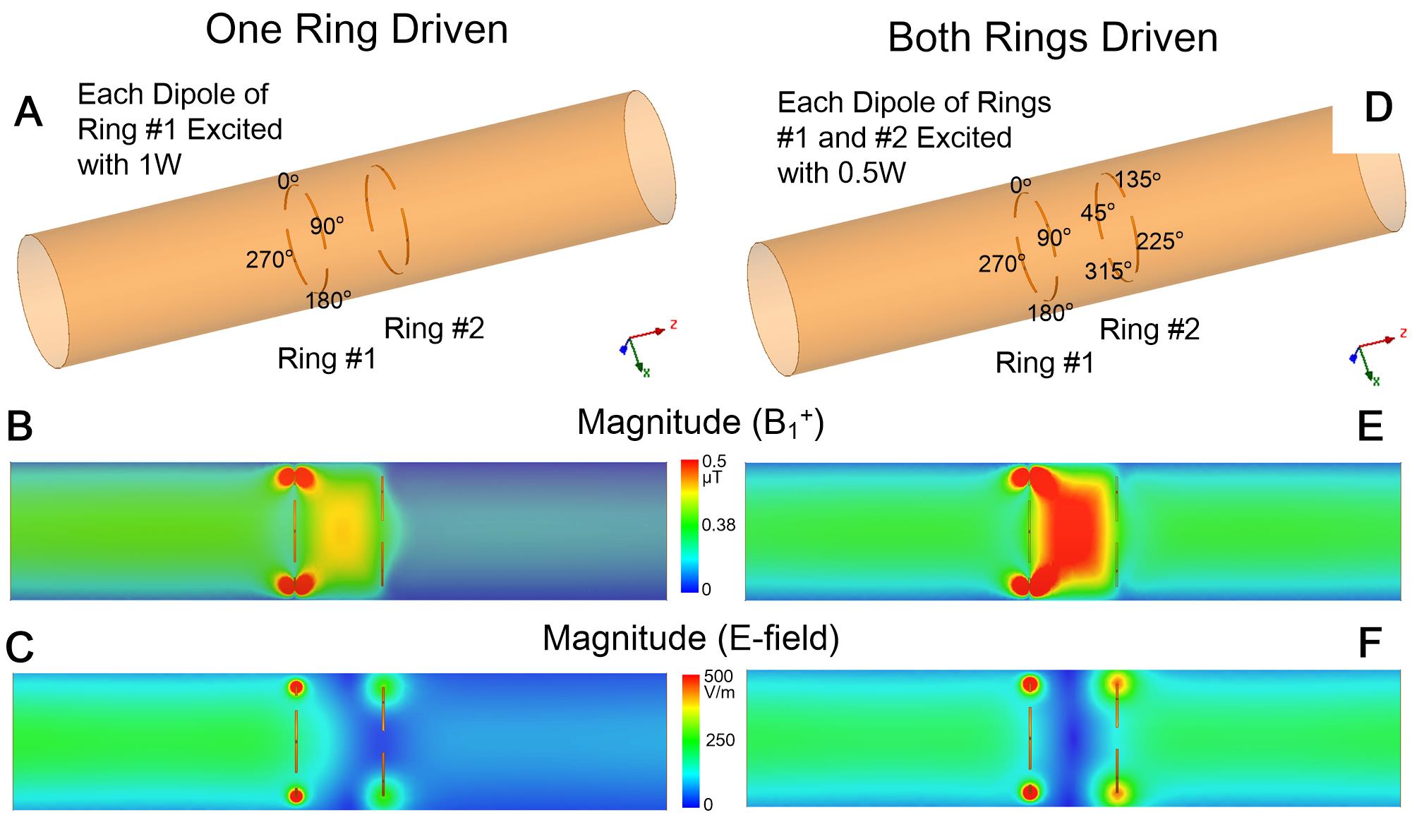
2. Driving one ring versus both rings
Fig. 3 compares B1 and E-fields that arise when driving one ring versus both rings in differential-current mode. It is found that driving both rings increases the B1 field and reduces the E-field, indicating higher efficiency and lower SAR. This can be attributed to the fact that the two rings produce parallel magnetic (H-) field but opposite electric (E-) field in the standing-wave region when driven in differential-current mode.
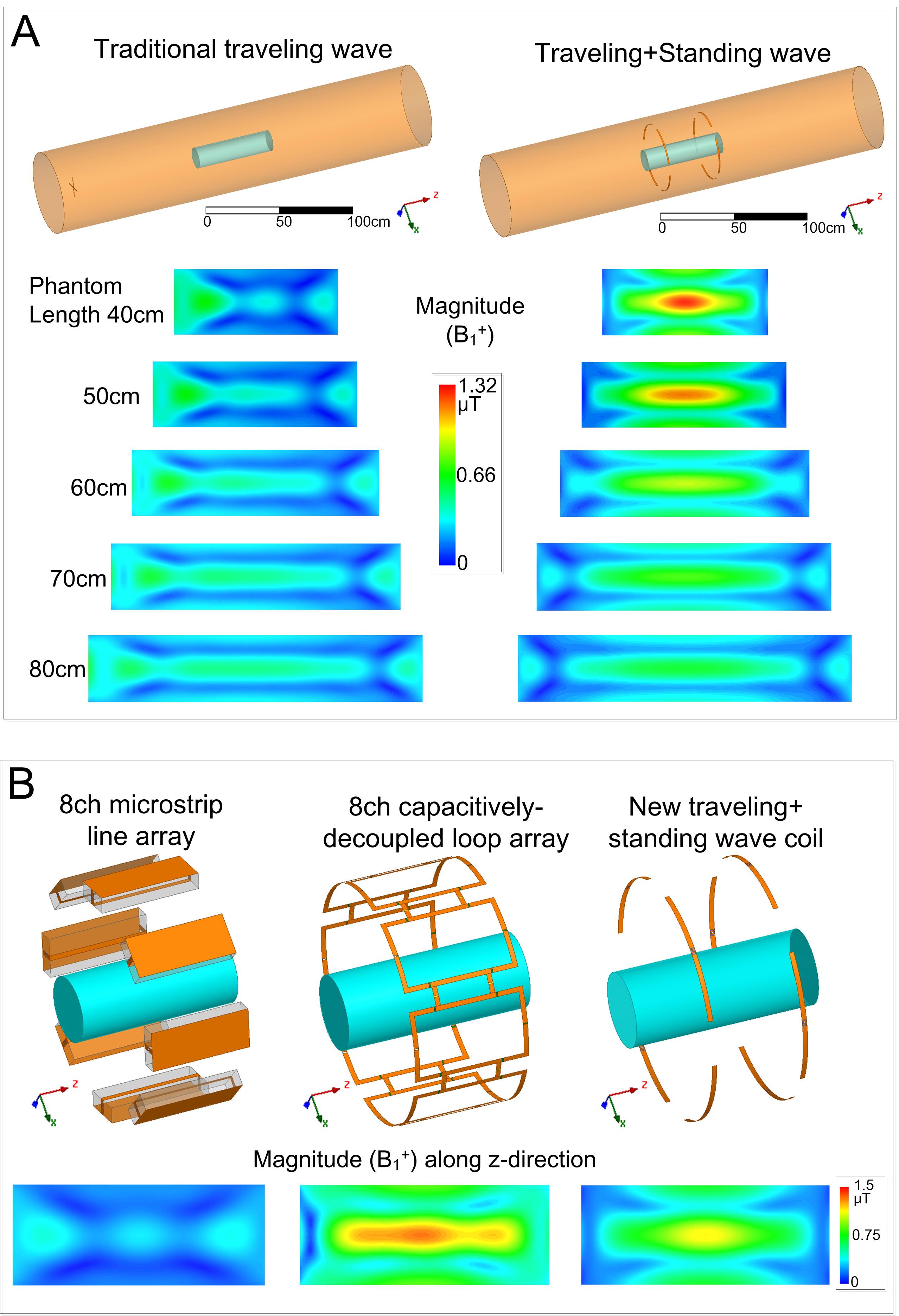
3. Comparison with conventional traveling-wave and standing-wave coils
The transmit efficiency of this new coil (when both rings are driven) was then compared to traditional traveling-wave MRI4 and standing-wave MRI using loop and stripline coils1. For all cases, the total input power was set to 8W and equally divided to each coil element. A cylindrical phantom (16 cm diameter, б=0.6 S/m and ξr=78) was placed at the center of the MR bore. Each stripline element was made of Teflon bar (25x10x4 cm3). Each loop element had a dimension of 25x16 cm2 and adjacent loops were decoupled by capacitive networks.
Results
Fig. 4A compares the new coil with a traditional traveling-wave arrangement. For longer coverage (60 cm), the new coil has slightly higher efficiency than traditional traveling-wave. However, the efficiency is much higher for shorter coverage (20 cm). Fig. 4B compares the results with stripline and loop arrays. The average transmit efficiency of the new coil was 24% lower than the loop array and 140% higher than the stripline array. The low efficiency of the stripline coils can be attributed to its confined electromagnetic field and the large distance between the coil and the phantom. Fig. 5 shows B1 fields using individual elements of the new coil. Their distinct patterns suggest that they may be effective for parallel transmission and parallel imaging at 7T.Discussion and Conclusion
In this work, a novel 7T transmit coil was described with adjustable longitudinal coverage. Cross-talk between the two rings is relatively low (<-14 dB), so all elements do not need to be re-tuned or re-matched when the distance between the rings is adjusted. It is found that adjacent dipoles in the same ring have the highest coupling (-7 dB), which may decrease the transmit efficiency to some extent. One possible solution is to shorten their length (using lump-element inductors or a dielectric coating) and thus increase their distance from each other. An alternative solution is to use decoupling treatments to reduce the coupling. Further work will focus on solving the coupling problem and fabricating practical coils to validate these simulation results.Acknowledgements
This work was supported by NIH R01 EB 016695 and NIH R21 EB 018521.References
1. Adriany, G., Van de Moortele, P.-F., Wiesinger, F., Moeller, S., Strupp, J. P., Andersen, P., Snyder, C., Zhang, X., Chen, W., Pruessmann, K. P., Boesiger, P., Vaughan, T. and Ugurbil, K. (2005), Transmit and receive transmission line arrays for 7 Tesla parallel imaging. Magn Reson Med, 53: 434–445. doi: 10.1002/mrm.20321
2. Chang, G., Wiggins, G. C., Xia, D., Lattanzi, R., Madelin, G., Raya, J. G., Finnerty, M., Fujita, H., Recht, M. P. and Regatte, R. R. (2012), Comparison of a 28-channel receive array coil and quadrature volume coil for morphologic imaging and T2 mapping of knee cartilage at 7T. J. Magn. Reson. Imaging, 35: 441–448. doi: 10.1002/jmri.23506
3. Raaijmakers, A. J. E., Ipek, O., Klomp, D. W. J., Possanzini, C., Harvey, P. R., Lagendijk, J. J. W. and van den Berg, C. A. T. (2011), Design of a radiative surface coil array element at 7 T: The single-side adapted dipole antenna. Magn Reson Med, 66: 1488–1497. doi: 10.1002/mrm.22886
4. Brunner DO, De Zanche N, Frohlich J, Paska J, Pruessmann KP. Travelling-wave nuclear magnetic resonance. Nature. 2009;457:994–998.
5. Webb, A. G., Collins, C. M., Versluis, M. J., Kan, H. E. and Smith, N. B. (2010), MRI and localized proton spectroscopy in human leg muscle at 7 tesla using longitudinal traveling waves. Magn Reson Med, 63: 297–302. doi: 10.1002/mrm.22262
6. R. Schmidt; A. Webb, "Characterization of an HEM-mode dielectric resonator for 7 T human phosphorous magnetic resonance imaging," in IEEE Transactions on Biomedical Engineering, in press, doi: 10.1109/TBME.2016.2533659
7. S. Uda and Y. Mushiake, Yagi-Uda Antennas 1954 Maruzen Co.
Figures