4289
Design of Elliptical Birdcage Coil with Constant Ring-capacitor Value1R&D Group, Hitachi, Ltd., Kokubunji, Japan, 2Healthcare Business Unit, Hitachi, Ltd., Tokyo, Japan
Synopsis
The value of ring capacitors in elliptical birdcage coil (EBC) should be varied gradually according to the location of the ring capacitor in order to generate uniform B1+ field distribution. Usually, it is difficult to adjust the value of the ring capacitor precisely by using fixed capacitors, because the value of the fixed capacitor is discretized. To realize the easy fabrication of EBC, we have designed EBC with constant ring-capacitor value at 1.5T. Simulation and experimental results indicated that the designed EBC generated uniform B1+ field distribution and showed the same transmission efficiency as the conventional EBC.
Introduction
To generate uniform B1+ field distribution by an elliptical birdcage coil (EBC), the value of ring capacitors in EBC should be varied gradually according to the location of the ring capacitor.1,2 It is difficult to adjust the value of the ring capacitor precisely by using fixed capacitors, because the value of the fixed capacitor is discretized. If the ring-capacitor value of EBC is constant, it is easy to fabricate EBC which generates uniform B1+ field distribution. To realize the easy fabrication of EBC, we have designed EBC with constant ring-capacitor value by changing the position and dimensions of the rung elements in EBC. We also evaluated the uniformity of B1+ field distribution generated by the designed EBC at 1.5T.Methods
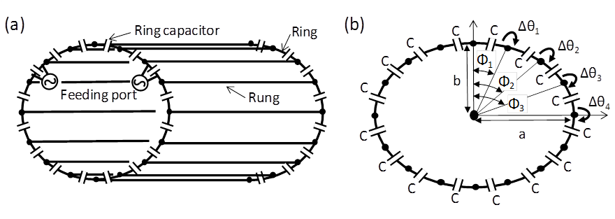
Coil Design: Figure 1 shows the structure of EBC with constant ring-capacitor value. We analyzed the condition of circuit parameters which generated uniform B1+ distribution by the equivalent circuit analysis under the condition that all values of ring capacitors were identical. As a result, we found that EBC with constant ring-capacitor value generated uniform B1+ distribution when the dimensions and circuit parameters satisfied the following equations;
$$\Phi_{m}=\tan^{-1}(\frac{b}{a}\tan(\sum_{k=1}^m\frac{\triangle {\theta}_{k}+\triangle {\theta}_{k+1}}{2}))$$
$$\cos(\triangle\theta_{k+1})=1+\frac{1}{L_{k+1}^l}((L_{k}^r-L_{k-1}^r)+L_{k-1}^l(\cos(\theta_{k-1})-1))$$
$$\sin(\triangle\theta_{k+1})=\frac{L_k^l}{L_{k+1}^l}\sin(\triangle\theta_{k})$$
$$\sum_{k=1}^N(\triangle\theta_{k}+\triangle\theta_{k+1})=2\pi$$
where Lrk and Llk are k-th ring and rung inductances, respectively. Φm is angle of m-th rung shown in Fig. 1. N is total number of rungs. Δθk is k-th phase difference between adjacent two ring capacitors as shown in Fig. 1. a and b are lengths of major and minor axes in the ring element of EBC, respectively. Lrk, Llk, Φm, and Δθk were calculated from numerical simulation.3 The width of ring can be calculated from the obtained Lrk. The width of rung can be calculated from Llk and the length of rung (lr). The ring capacitor value C can be determined by a resonant frequency of EBC. Based on the above equations, we have designed EBC with constant ring-capacitor value under the conditions with resonant frequency of 63.86MHz (1.5T), N=22, a/b=1.15, a=375mm, and lr = 500mm.
Simulations: Our own program3 which was based on the method of moments was used for numerical simulations. This program can calculate the B1+ distribution generated by RF coil. The value of B1+ in the numerical simulation was defined by the B1+ field generated when a signal of 1W was fed to the coil.
Evaluation: To confirm the resonant mode of the designed EBC, its current distribution was evaluated by numerical simulation. Isolation between two feeding ports of the EBC was also evaluated. To evaluate the uniformity of B1+ distribution, B1+ distribution of the designed EBC with quadrature drive (QD) was calculated under the unloaded condition. Uniformity of B1+ distribution (UNEMA) was evaluated with the NEMA standard. 5 The transmission efficiency of the designed EBC was compared to that of conventional EBC1 under the same coil dimensions. We also fabricated the EBC with constant ring-capacitor value and acquired B1+ map of cylindrical oil phantom (φ:300mm) using double angle method.4
Results & Discussion
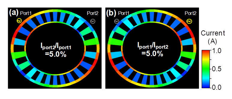
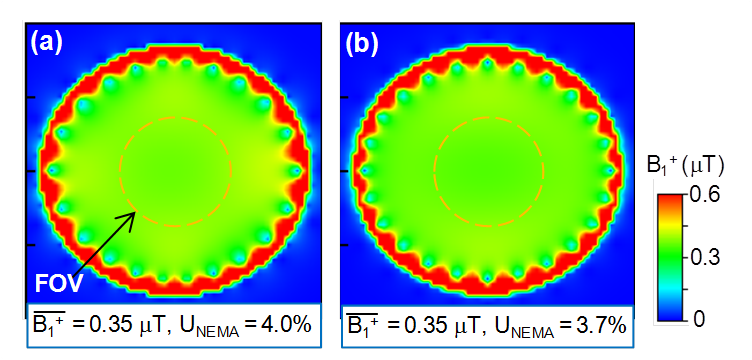
Simulation results: Figure 2 shows the current distribution of the designed EBC. The ring current at the un-driven port showed the minimum value. Ratio of the current at Port #2 to that at Port #1 (Iport2/Iport1) was 5.0% in Fig. 2a. In Fig. 2b, Iport1/Iport2 was also 5.0%. These results indicated that the designed EBC had good isolation between two feeding ports. Figure 3 shows B1+ distributions by the designed EBC and the conventional EBC at axial mid-plane of EBC, respectively. UNEMA of B1+ distribution by the designed EBC and the conventional EBC were 4.0% and 3.7% in the 30 cm FOV, respectively. These results indicated that there were no differences in B1+ uniformity between the designed EBC and the conventional EBC. The averaged value of B1+ distribution by the designed EBC and the conventional EBC was 0.35μT in the 30cm FOV. This result indicated that the transmission efficiency of the designed EBC was identical to that of the conventional EBC.
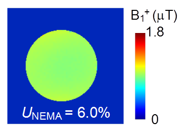
Experimental results: Figure 4 shows B1+ map of cylindrical oil phantom at axial mid-plane. The uniform B1+ distribution was acquired by the fabricated EBC with QD. B1+ map of the oil phantom showed UNEMA of 6.0% in the 30 cm FOV. It is considered that the difference in UNEMA between simulation and experiment is caused by the fabrication error of the designed EBC.
Conclusion
We have designed elliptical birdcage coil (EBC) with constant ring-capacitor value and evaluated the uniformity of B1+ distribution. Designed EBC showed uniform B1+ field distribution and the same transmission efficiency as the conventional EBC.Acknowledgements
No acknowledgement found.References
1. S. Li, et. al., Magn. Reson. Med., Vol. 37, pp.600-608, (1997)
2. M.C. Leifer, Magn. Reson. Med., Vol. 38, pp.726-732, (1997)
3. H. Ochi, et al., SMRM 11th Annual Meeting, 4021 (1992)
4. Strollberger, Magn. Reson. Med., Vol. 35, pp.246-251, (1996)
5. NEMA Standard Publications. MS 1 (1988)
Figures