4285
Simulation of B1 Efficiency in 64-Channel Phased Head Arrays at 7T and 10.5T.1CMRR University of Minnesota, Minneapolis, MN, United States, 2Life Services, LLC, Minneapolis, MN, United States
Synopsis
Simulation results are presented for 64-channel phased arrays operating at frequencies of 296.5 MHz (7T) and 447 MHz (10.5T) with 4.5 cm element loop diameters. FDTD simulations were performed per channel to obtain B1 receive fields of the coil array placed around a 2 mm resolution voxel anatomical head model. Sum-of-squares B1 efficiency maps show improved performance of the array at 10.5T compared to 7T over the whole head region.
Intro
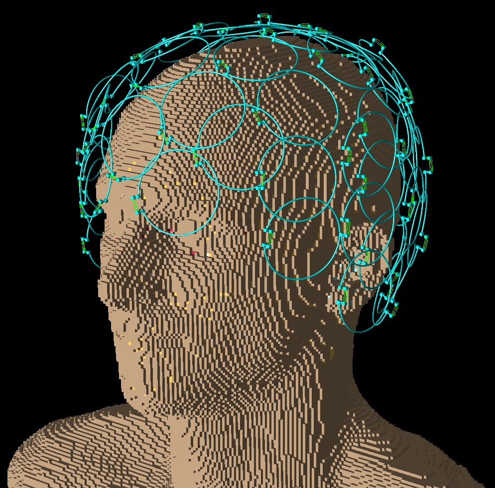
A method for increasing signal-to-noise ratio (SNR) for MRI imaging and spectroscopy is to decrease the coil size and increase the number of coils in an receive array1. Operating frequency and rf loading present constraints for optimal design for elements within an array2. Therefore, an engineering tradeoff exists between the number of channels and optimal element design for of a physically realizable phased array operating at a given frequency and loading condition. To explore this design tradeoff, B1 receive efficiency has been modeled for a 64-channel receive coil array for proton Larmor resonance frequencies corresponding to B0 of 7T (296.5 MHz) and 10.5T (447 MHz). The array under investigation consists of 64 individual receive elements with partially overlapping, 4.5 cm diameter coil loops. The elements are contained in a close fitting coil housing that conforms to the shape of a human head3.Methods
Remcom XFdtd (Remcom, Inc, State College, PA) was used to construct a simplified CAD representation of the array elements and perform finite-difference time-domain (FDTD) B1 field calculations4 in the presence of an anatomical voxel model. The XFdtd scripting interface was used to automate large portions of the coil positioning, voxel model alignment, and simulation generation. Postprocessing of XFdtd results was performed with a custom Python module. For simplicity, the circuit board of each element was replaced with a simplified tune and match feed structure and the plastic housing structures, cabling, etc. were ignored. Positions and orientations of the loops were extracted from CAD models of the receive array housing3 and were manually adjusted to ensure loop elements were electrically isolated. The array was loaded with the “Duke” Virtual Population voxel model with 2 mm voxel resolution.
Tuning and matching of loop elements was performed using the Remcom Circuit Element Optimizer (CEO) cosimulation tool in XFdtd5. This allowed tune and match capacitor values to be determined while including effects of neighboring coils and loading. Magnetic field values were calculated by individually exciting each channel in the receive coil array and terminating the remaining channels. The receive B1 fields for each channel were obtained from complex, steady-state B1x and B1y field components of the simulated magnetic fields: B1- = (B1x* - jB1y*)/2, where (*) indicates the complex conjugate. The B1 efficiency maps were constructed by weighting and combining the individual B1 receive fields using the sum-of-squares method6.
Results and Discussion
FDTD simulations of a 64-channel coil array with fixed element loop diameter has shown improved B1 efficiency of the receive array at 10.5T over the entire head region compared to 7T. The techniques presented can be used for simulation-driven design of coil arrays. FDTD simulations of a 64-channel phased array requires approximately two weeks of simulation time on a system with dial NVIDIA Tesla K40M GPU accelerators. Since many of the simulation steps are scripted, it is possible to perform parameterized studies based loop element and array parameters.Acknowledgements
P41 EB015894
S10 RR026783 “Multichannel Transmit Frontend for 7 Tesla” WM KECK Foundation
S10 RR029672 “Console for 10.5 Tesla Whole Body MRI System”
References
[1] P. B. Roemer, W. A. Edelstein, C. E. Hayes, S. P. Souza, and O. M. Mueller, “The NMR phased array.,” Magn. Reson. Med., vol. 16, no. 2, pp. 192–225, 1990.
[2] R. Lattanzi and D. K. Sodickson, “Ideal Current Patterns Yielding Optimal SNR and SAR in Magnetic Resonance Imaging: Computational Methods and Physical Insights,” Magn. Reson. Med., vol. 68, no. 1, pp. 286–304, 2012.
[3] Adriany, G., Schillak, S., Waks, M., Tramm, B., Grant, A., Yacoub, E., Vaughan, J. T., Olman, C., Schmitter, S. & Ugurbil K. “A Modular 16 Ch. Transmit/ 32 Ch. Receive Array for Parallel Transmission and High Resolution fMRI at 7 Tesla” in ISMRM Vol. 1 622 (Toronto, 2015).
[4] K. S. Yee, “Numerical solution of initial boundary value problems involving Maxwell’s equations in isotropic media,” IEEE Trans. Antennas Propag., vol. 14, no. 3, pp. 302–307, 1966.
[5] Remcom Inc., State College, PA “Overview of XFdtd ’ s Circuit Element Optimizer,” 2015. http://www.remcom.com/articles-and-papers/overview-of-xfdtds-circuit-element-optimizer.html.
[6] W. A. Edelstein, O. M. Mueller, R. L. Frey, and D. M. Vatis, “SMRM 6th Annual Meeting,” p. 372, 1987.
Figures